Additional interior LED lights

 02-13-2015, 03:28 PM
#72
JK Junkie
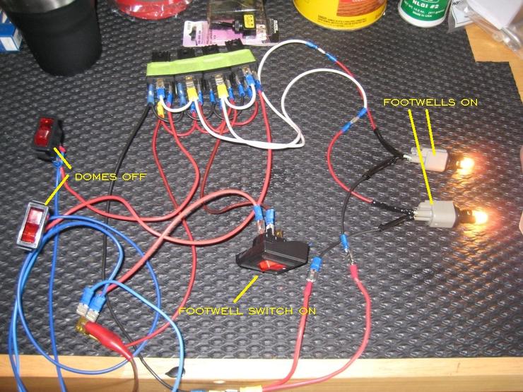
It looks worse than it is. It's mostly just jumpers between relays. Jump all the pin 30s together. Jump two pin 87s together twice. Jump all pin 86s together. Jump 2 pin 85s together and then run 2 wires for the other 2. If you don't have much experience with wiring it can seem daunting. And I understand that. But whichever way you decide to go, you CAN do it. I got your back. I will walk you through it.
You are going to need crimpers for the 3 way switches or relays, and a soldering iron for the diodes. Do you have either of those?
You are going to need crimpers for the 3 way switches or relays, and a soldering iron for the diodes. Do you have either of those?
Last edited by 14Sport; 02-13-2015 at 03:44 PM.
02-15-2015, 07:03 AM
#73
JK Junkie
Sorry Grand Umpah, not trying to hijack your thread. Lange, if you want to start a thread for the footwells I will repost in that one and delete this one.
I tested the relay schematic option just to make sure it works and it does. I will have to pick up some diodes to test that version if you want. Anyway, as you can see from the pictures, most of the wiring is just between the relays, which I taped together to keep everything tidy. If I was installing this, I would zip tie them instead.


I tested the relay schematic option just to make sure it works and it does. I will have to pick up some diodes to test that version if you want. Anyway, as you can see from the pictures, most of the wiring is just between the relays, which I taped together to keep everything tidy. If I was installing this, I would zip tie them instead.
Last edited by 14Sport; 02-15-2015 at 07:07 AM.
02-17-2015, 11:57 AM
#74
JK Newbie

Join Date: Jan 2012
Location: Washington, MO
Posts: 25
Likes: 0
Received 0 Likes
on
0 Posts
14SPORT: Thanks for all this help! I like the diode option since it's less wires running round but the relay option seems fairly simple to do but with a lot of connectors and splicing. I have crimpers and I can solder so either option is doable. I guess I don't know anything about diodes in reality. I know that the voltage is an issue and there is a direction in which the current flows through them. But I don't know where I would get them or even what type to get.
02-17-2015, 12:54 PM
#75
JK Junkie
14SPORT: Thanks for all this help! I like the diode option since it's less wires running round but the relay option seems fairly simple to do but with a lot of connectors and splicing. I have crimpers and I can solder so either option is doable. I guess I don't know anything about diodes in reality. I know that the voltage is an issue and there is a direction in which the current flows through them. But I don't know where I would get them or even what type to get.
http://www.amazon.com/gp/product/B00...?ie=UTF8&psc=1
Also, there's a trick to soldering them inline in a wire. The leads can be very fragile and break easily from movement if not properly soldered. I can post some pics after I get the diodes of the technique I learned and use. It will involve heat shrinking. I got 3A instead of 1a because the leads are thicker and less fragile.
02-24-2015, 11:55 AM
#76
JK Newbie
Join Date: Jan 2012
Location: Washington, MO
Posts: 25
Likes: 0
Received 0 Likes
on
0 Posts
02-24-2015, 12:04 PM
#77
JK Junkie
I think it's just a couple of screws to drop the light. Maybe four. Once it's dropped you should have access to the back.
02-24-2015, 06:39 PM
#78
JK Newbie
Join Date: Feb 2015
Location: Farmington, NM
Posts: 76
Likes: 0
Received 0 Likes
on
0 Posts
14Sport, you're awesome. It's really cool to see someone so enthusiastic to help others out and walk them through this kind of project! I know there are a lot of people out there (like myself) with only a basic understanding of simple circuit design like this, so having someone to walk through the basics and cut out a lot of the guesswork is really valuable.
I plan to adapt some of these circuits for a specialized application... haven't decided on all the details yet (but it involves rock lights, dome, footwell, and some others). I may or may not drop some noob questions on you when I get to that point!
Thanks a ton!!!

I plan to adapt some of these circuits for a specialized application... haven't decided on all the details yet (but it involves rock lights, dome, footwell, and some others). I may or may not drop some noob questions on you when I get to that point!
Thanks a ton!!!
02-25-2015, 02:05 AM
#79
JK Junkie
14Sport, you're awesome. It's really cool to see someone so enthusiastic to help others out and walk them through this kind of project! I know there are a lot of people out there (like myself) with only a basic understanding of simple circuit design like this, so having someone to walk through the basics and cut out a lot of the guesswork is really valuable.
I plan to adapt some of these circuits for a specialized application... haven't decided on all the details yet (but it involves rock lights, dome, footwell, and some others). I may or may not drop some noob questions on you when I get to that point!
Thanks a ton!!!
I plan to adapt some of these circuits for a specialized application... haven't decided on all the details yet (but it involves rock lights, dome, footwell, and some others). I may or may not drop some noob questions on you when I get to that point!
Thanks a ton!!!
I know many people are afraid of doing small electrical projects like this and I'm trying to show them that they can do it. I wish someone had showed me when I was younger. But at the same time, I want them to do it right and not burn their Jeep down.
And for those who don't know and are interested, this project was continued in Lange's original thread that we brought back from the dead.
https://www.jk-forum.com/forums/jk-e...h-side-296351/
Last edited by 14Sport; 02-25-2015 at 02:45 AM.
03-23-2015, 05:07 PM
#80
JK Enthusiast
I did this modification today and it works great!  You can read my write-up here: https://www.jk-forum.com/forums/jk-s...6/#post4074815
Here is a couple pictures of the completed project!


Thanks for the idea!!
You can read my write-up here: https://www.jk-forum.com/forums/jk-s...6/#post4074815Here is a couple pictures of the completed project!


Thanks for the idea!!

