Easy Switched Power Source
 09-06-2015, 03:32 PM
#91
JK Jedi Master
Thread Starter
In the ways I show the tap installed at the beginning of this thread, the part you have outlined in red is part of the battery bus, or the accessory bus. The other leg goes out to the load. So, the wire at the top of the tap isn't part of the original load circuit.
 09-06-2015, 04:21 PM
#92
JK Junkie
So there are two different paths from the bus up the left pin to the fuses? I didn't know that. I haven't pulled one apart. That's awesome and quite an ingenious idea. I'm guessing split with an isolator in between. Thanks for letting me know. That one little bit always made me cautious.  Not an issue when tapping an empty slot but always a consideration for me when tapping an occupied slot.
Not an issue when tapping an empty slot but always a consideration for me when tapping an occupied slot.
Last edited by 14Sport; 09-06-2015 at 04:24 PM.
09-06-2015, 04:41 PM
#93
JK Jedi Master
Thread Starter
So there are two different paths from the bus up the left pin to the fuses? I didn't know that. I haven't pulled one apart. That's awesome and quite an ingenious idea. I'm guessing split with an isolator in between. Thanks for letting me know. That one little bit always made me cautious. Not an issue when tapping an empty slot but always a consideration for me when tapping an occupied slot.
Not an issue when tapping an empty slot but always a consideration for me when tapping an occupied slot.Both fuses are connected to the left leg in the picture. The bottom fuse sends power out the right leg to the original circuit. The top fuse sends power out the wire to an added circuit. Neither circuit adds a load to the other. The bus, which feeds the left leg, sees both loads, but it is a steel bus bar, making overloading the bus virtually impossible.
09-06-2015, 04:51 PM
#94
JK Junkie
I'm not sure what you mean.
Both fuses are connected to the left leg in the picture. The bottom fuse sends power out the right leg to the original circuit. The top fuse sends power out the wire to an added circuit. Neither circuit adds a load to the other. The bus, which feeds the left leg, sees both loads, but it is a steel bus bar, making overloading the bus virtually impossible.
Both fuses are connected to the left leg in the picture. The bottom fuse sends power out the right leg to the original circuit. The top fuse sends power out the wire to an added circuit. Neither circuit adds a load to the other. The bus, which feeds the left leg, sees both loads, but it is a steel bus bar, making overloading the bus virtually impossible.
09-06-2015, 05:00 PM
#95
JK Jedi Master
Thread Starter
Yes, but keep in mind, the right side of the tap can carry only what the top wire can handle, plus whatever the original circuit's wire under the TIPM can handle. Those two limiting factors are a lot less than what the bus can supply.
09-06-2015, 07:56 PM
#97
JK Enthusiast
So my aux. light switch only has a 2 amp fuse in it and the rear outlet is 20 amp so running both on the M7 slot should be fine, correct?
09-07-2015, 02:28 AM
#98
JK Jedi Master
Thread Starter
 01-10-2017, 06:42 PM
#100
JK Freak
If your TIPM (fuse box) is set up like my 2008 is....
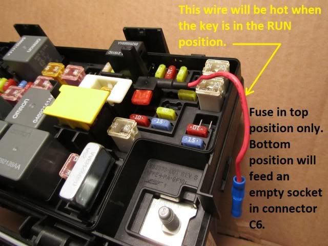
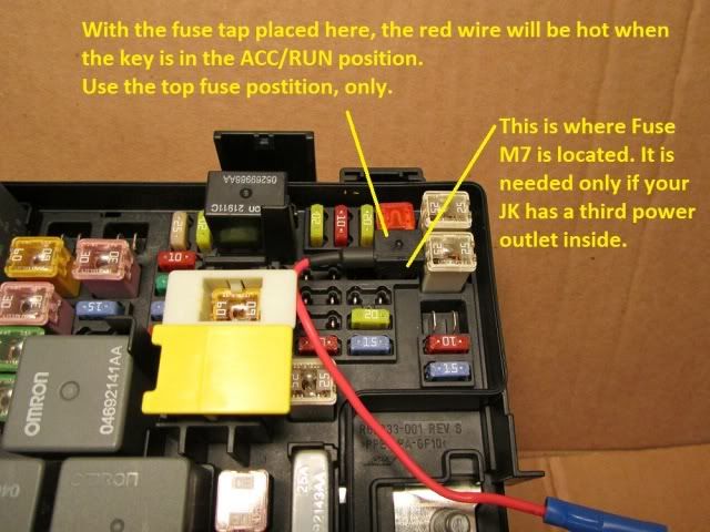
Here is a way to get switched power from the fuse box. It's easier than installing wires in the connector under the TIPM, although not quite as clean an install.
The fuse tap came from Advance Auto, Buss catalog # BP/HHH. It is rated for 10 amps, so that will be the max fuse you should put in it. (edit: I have seen them rated as high as 30 amps, too.)
For use as outlined, only the top fuse position can be used, as the bottom fuse would send power to an empty wire socket in TIPM connector C6.
Score, thank you sir! Now I won't kill the battery again!