When you click on links to various merchants on this site and make a purchase, this can result in this site earning a commission. Affiliate programs and affiliations include, but are not limited to, the eBay Partner Network.
powertrain control module pin-out diagram for o2 sensor
JK Electrical, Lighting & Sound SystemsBulletin board forum regarding topics such as stereo head units, CD players, MP3 players, speaker systems, amplifiers, hardmounted GPS devices, computers, headlight upgrades, fog lights, off-road lights, general wiring and anti-theft devices.
powertrain control module pin-out diagram for o2 sensor
I'm looking for the driver side o2 sensor wires on the connector of the PCM. I want to jump the factory wiring harness at each sensor and wire directly to the powertrain control module. I suspect something is wrong between the sensors and PCM. I'm getting an intermittent code of P0430 and want to solve or rule out wiring problems. I will start with the after cat, sensor left (item 4) first.
@RONJENX, I'd appreciate your assistance. I can't locate the number of the wires. I found several of your posts about the PCM but none specifically with the wiring pin-out.
@RonJenx I appreciate the fast response. I think something is up with the wiring harness though. It's probably a small nick or worn spot on a wire with this circuit. I had a similar problem with the Throttle body and accelerator pedal. There is a check for deviation on both and I was getting an intermittent code for a difference in them. I replaced the pedal assembly first. I still would get a code. I replaced the Throttle body. Still the code would come up intermittent. A dealer tech gave the suggestion to rewire the harness between the throttle body and PCM. The problem has never appeared again.
I have replaced both o2 sensors on this bank and checked the plugs for damage. I can reset the MIL code P0430 and it goes away for a while but reappears.
I'm going to do this first. If it doesn't stop the code, next I'm going to wire around the plugs to eliminate that connection. Last idea I have is using a spark plug no fouler to pull the sensor out of the exhaust flow.
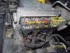
@ronjenx I finally dived into fixing the ML code of P0430 inefficiency between upper and lower bank 2 - O2 sensors. I first checked continuity at the plug and pins at PCM with your pin out diagram. There was no issue detected. I proceed anyhow and cut off the plug at the lower O2 sensor and cut the wires at the PCM and created a new direct harness from PCM to the lower O2 sensor. The problem seemed to go away with code P0430. However, while checking the live O2 sensor feeds on a mobile OBD reader, the bank 1 lower O2 sensor (pictured below on the lower right) seems to have stopped reading . All I can figure there's a shared wire between both lower O2 sensors. You can see its still receiving voltage but not moving. Code P0137 (O2 sensor low voltage, bank 1 sensor 2) appeared after 2mins of driving.
Can you confirm the Bank 1 lower pin out? I believe i'm going to have to splice back in one of the wires I cut. I'll start this afternoon checking continuity between bank 1 lower sensor and cut wires at PCM. That will confirm my idea but I wanted to know what you thought.
The two lower sensors share a return line. (Pin 3 on each sensor.)
Bank 2 lower returns directly to C1 pin 32 of the PCM. Bank 1 lower taps into that circuit somewhere before the PCM.
If you cut the return wire from 2/2, you also cut off 1/2's return.
@ronjenx Do you have the pin out for bank 1 sensor 2. My problem with P-0430 has not been fixed. I'm testing some theories and could use this information, Thank you again.
 02-27-2017, 10:24 AM