Switchable Aux Reverse Lights - Schematic Feedback Requested
 02-03-2015, 09:01 AM
#1
JK Junkie
Thread Starter
I'm trying to refine a couple of schematics for the guys that want switchable reverse lights but don't want to solder in diodes, since I see a lot of posts looking for this. I'm hoping to get some feedback from those more knowledgeable with the Jeep wiring than I.
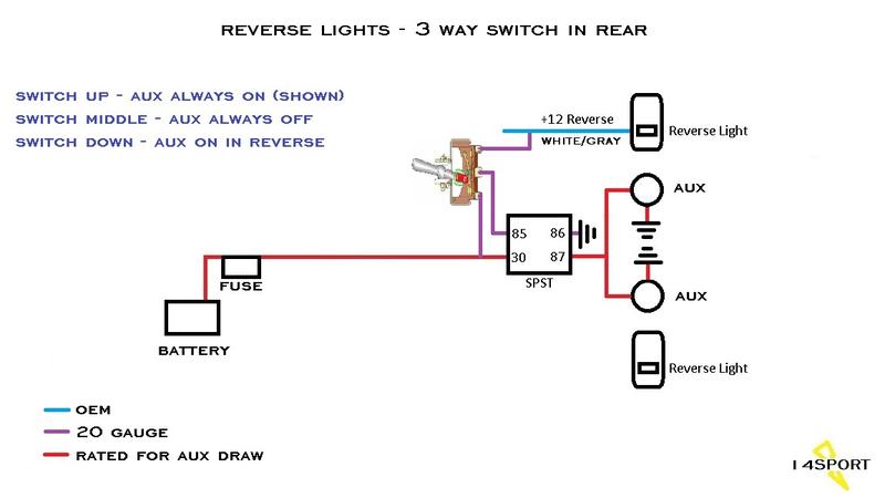
This first one is for the overlanders who want to be able to use the lights when camping. It includes a 3 position switch in the rear that allows them to flick them on whenever they need to. I'm pretty sure this will work as designed.
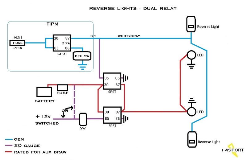
This next one is for the guys that aren't interested in using a 3 position switch because they use Conturas or regular toggles. It's a dual relay design that will cut the power feed from the reverse circuit when the switch is turned on. This will also turn on the reverse light though but won't backfeed the reverse circuit. I'm wondering if this will cause both reverse lights to turn on or just the one?

Any and all feedback is appreciated.
Edit: In case you don't wish to read through the entire thread, this is the final dual relay version we ended with.
This first one is for the overlanders who want to be able to use the lights when camping. It includes a 3 position switch in the rear that allows them to flick them on whenever they need to. I'm pretty sure this will work as designed.
This next one is for the guys that aren't interested in using a 3 position switch because they use Conturas or regular toggles. It's a dual relay design that will cut the power feed from the reverse circuit when the switch is turned on. This will also turn on the reverse light though but won't backfeed the reverse circuit. I'm wondering if this will cause both reverse lights to turn on or just the one?
Any and all feedback is appreciated.
Edit: In case you don't wish to read through the entire thread, this is the final dual relay version we ended with.
Last edited by 14Sport; 02-10-2015 at 05:52 AM.
 02-03-2015, 09:14 AM
#2
JK Enthusiast
Join Date: Jan 2015
Location: Des Moines
Posts: 111
Likes: 0
Received 0 Likes
on
0 Posts
Nice Job 14 Sport! 
depending on where you tap into the factory wiring, that should light up both factory reverse lights
depending on where you tap into the factory wiring, that should light up both factory reverse lights
Last edited by pvanweelden; 02-03-2015 at 09:17 AM.
02-03-2015, 09:32 AM
#3
JK Junkie
Thread Starter
Thanks. You have to tie into the oem reverse circuit at the tail light assembly. Someone in another thread tried to tie in up near the front and it wasn't working. He changed it to the rear and it worked. It seems like the wire that feeds the reverse lights also feed the brake or tail lights until it reaches the housing.
02-03-2015, 02:33 PM
#4

Thanks for this. Am getting ready to wire in rear aux lights and was trying to figure out how I'd be able to have them both come on when in reverse, and also switch activated when desired. I want both the reverse and aux lights to come on when in reverse, and then only the aux lights to come on when I hit the switch, so I think your 2nd schematic (with optional diode) is exactly what I was looking for.
So with the second diagram (dual-relay setup), which diode do I use? Are there diodes specific to 12v vs. 120v, or AC vs. DC applications, or are they just max amp rated? Does it just have to be rated at the max amp draw of my aux lights? I've never wired in a diode before. Need to do some research on use of diodes. Not sure if it's something my local Radio Shack will carry or if I need to special order one. Thanks again!
So with the second diagram (dual-relay setup), which diode do I use? Are there diodes specific to 12v vs. 120v, or AC vs. DC applications, or are they just max amp rated? Does it just have to be rated at the max amp draw of my aux lights? I've never wired in a diode before. Need to do some research on use of diodes. Not sure if it's something my local Radio Shack will carry or if I need to special order one. Thanks again!
02-03-2015, 05:52 PM
#5
JK Enthusiast
14Sport - I really enjoy studying your schematics and I download them all the time, just in case I need one some day. These both look good to me. Keep up the good work!
02-04-2015, 01:35 AM
#6
JK Junkie
Thread Starter
Thanks for this. Am getting ready to wire in rear aux lights and was trying to figure out how I'd be able to have them both come on when in reverse, and also switch activated when desired. I want both the reverse and aux lights to come on when in reverse, and then only the aux lights to come on when I hit the switch, so I think your 2nd schematic (with optional diode) is exactly what I was looking for.
So with the second diagram (dual-relay setup), which diode do I use? Are there diodes specific to 12v vs. 120v, or AC vs. DC applications, or are they just max amp rated? Does it just have to be rated at the max amp draw of my aux lights? I've never wired in a diode before. Need to do some research on use of diodes. Not sure if it's something my local Radio Shack will carry or if I need to special order one. Thanks again!
So with the second diagram (dual-relay setup), which diode do I use? Are there diodes specific to 12v vs. 120v, or AC vs. DC applications, or are they just max amp rated? Does it just have to be rated at the max amp draw of my aux lights? I've never wired in a diode before. Need to do some research on use of diodes. Not sure if it's something my local Radio Shack will carry or if I need to special order one. Thanks again!
The 3 way switch would work for you too. If you leave the switch in the down position the aux lights will come on with the reverse lights. Switch up to turn it on manually without the reverse lights when you need it. And switch middle if you're on the trail at night with someone behind you so you don't blind them if having to back up. Of course, the switch could be mounted up front as well.
Thanks, RC. Still trying to get them perfected. One member offered to send me the stock wiring diagram so I can tweak the designs as necessary. These are still in development stage at this point and may change once I know how OEM works.
02-04-2015, 03:00 AM
#7
JK Junkie
Thread Starter
One of my concerns has been backfeeding circuits when the switch is on and the Jeep is put into reverse. I'm starting to think that I don't need to worry about backfeeding the TIPM. If that's the case, then I can eliminate the SPDT relay and go simply with a diode. Something like this.
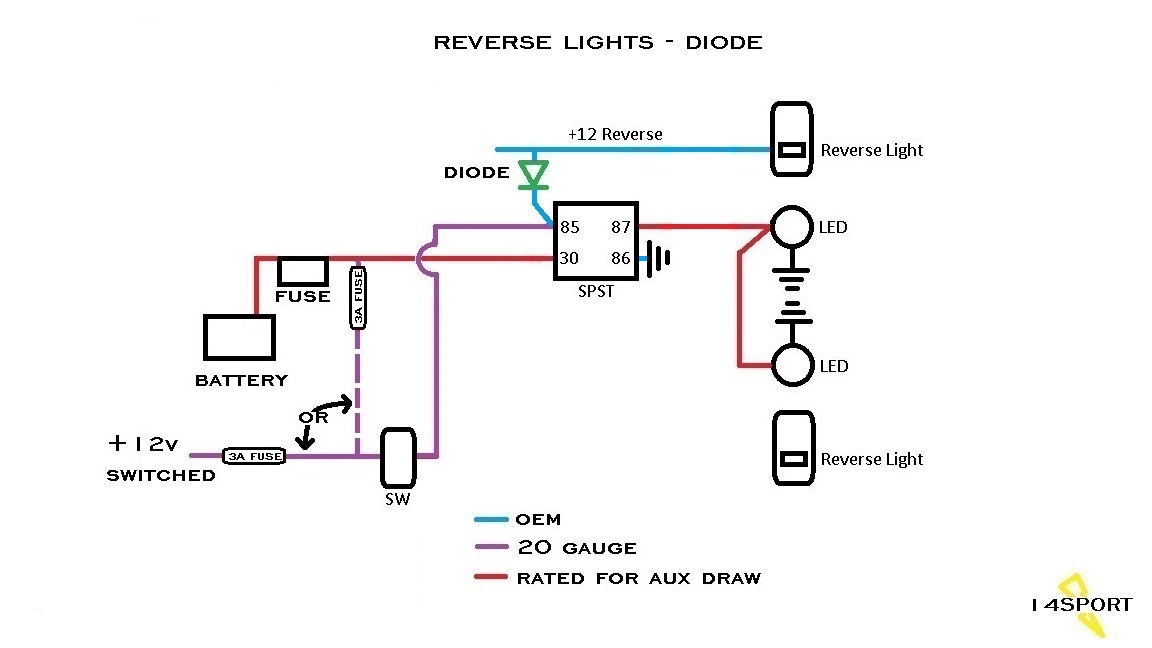
The diode would have to be rated for the reverse lights draw, since the draw from the control circuit is minimal. Without the diode the reverse lights could draw power through the control circuit (purple wire) when the switch is turned on. I suppose if you wanted the reverse lights to come on with the auxiliaries, then you could leave the diode out and make sure the control circuit wire is rated and fused for the draw of the reverse lights. One thing I always worry about is a short. By using the SPDT relay, if a short was to happen upstream on the oem reverse light circuit, you would not feed it from the control circuit. One of the things I do like about using the SPDT relay is when you activate the switch, you pretty much isolate all of this from the OEM wiring.
The diode would have to be rated for the reverse lights draw, since the draw from the control circuit is minimal. Without the diode the reverse lights could draw power through the control circuit (purple wire) when the switch is turned on. I suppose if you wanted the reverse lights to come on with the auxiliaries, then you could leave the diode out and make sure the control circuit wire is rated and fused for the draw of the reverse lights. One thing I always worry about is a short. By using the SPDT relay, if a short was to happen upstream on the oem reverse light circuit, you would not feed it from the control circuit. One of the things I do like about using the SPDT relay is when you activate the switch, you pretty much isolate all of this from the OEM wiring.
Last edited by 14Sport; 02-12-2016 at 02:08 AM.
Trending Topics
02-04-2015, 05:50 AM
#8
One of my concerns has been backfeeding circuits when the switch is on and the Jeep is put into reverse. I'm starting to think that I don't need to worry about backfeeding the TIPM. If that's the case, then I can eliminate the SPDT relay and go simply with a diode. Something like this.

The diode would have to be rated for the reverse lights draw, since the draw from the control circuit is minimal. Without the diode the reverse lights could draw power through the control circuit (purple wire) when the switch is turned on. I suppose if you wanted the reverse lights to come on with the auxiliaries, then you could leave the diode out and make sure the control circuit wire is rated and fused for the draw of the reverse lights. One thing I always worry about is a short. By using the SPDT relay, if a short was to happen upstream on the oem reverse light circuit, you would not feed it from the control circuit. One of the things I do like about using the SPDT relay is when you activate the switch, you pretty much isolate all of this from the OEM wiring.
The diode would have to be rated for the reverse lights draw, since the draw from the control circuit is minimal. Without the diode the reverse lights could draw power through the control circuit (purple wire) when the switch is turned on. I suppose if you wanted the reverse lights to come on with the auxiliaries, then you could leave the diode out and make sure the control circuit wire is rated and fused for the draw of the reverse lights. One thing I always worry about is a short. By using the SPDT relay, if a short was to happen upstream on the oem reverse light circuit, you would not feed it from the control circuit. One of the things I do like about using the SPDT relay is when you activate the switch, you pretty much isolate all of this from the OEM wiring.
I'm not following your concern about a short being fed by the control circuit using a SPDT relay. This solution you have here with a diode in place looks to isolate the aux lights from the OEM circuit even more than using a SPDT relay. I'm obviously not as smart on this as you though. I can read a schematic and know about enough to get me into trouble. Thanks for the work on this. I'll be fusing every 12v feed regardless. I imagine worst case is I have to change multiple fuses if one circuit isn't isolated from another enough to contain the short.
Why would the diode as you have it placed in this schematic have to be rated for the draw of the OEM reverse lights? The only draw through the diode in this new drawing would be the draw from activating the relay, which should be milliamps in this case, no? Certainly couldn't hurt to go overboard with the capacity of the diode so it doesn't burn up I suppose. I'm more curious than anything.
02-04-2015, 06:28 AM
#9
JK Junkie
Thread Starter
Oh, I like this new schematic even better. This looks to me to be just of good of a solution, and a simpler one at that. With the other setup I was thinking the diode needed to go between the OEM light at the AUX light feed. There is a small voltage loss through the diode as I understand it, which would result in a dimmer aux light, albeit probably a small difference and not that noticeable. I just like everything about this setup better.
I'm not following your concern about a short being fed by the control circuit using a SPDT relay. This solution you have here with a diode in place looks to isolate the aux lights from the OEM circuit even more than using a SPDT relay. I'm obviously not as smart on this as you though. I can read a schematic and know about enough to get me into trouble. Thanks for the work on this. I'll be fusing every 12v feed regardless. I imagine worst case is I have to change multiple fuses if one circuit isn't isolated from another enough to contain the short.
Why would the diode as you have it placed in this schematic have to be rated for the draw of the OEM reverse lights? The only draw through the diode in this new drawing would be the draw from activating the relay, which should be milliamps in this case, no? Certainly couldn't hurt to go overboard with the capacity of the diode so it doesn't burn up I suppose. I'm more curious than anything.

My concern, maybe not even valid which is why I'm throwing it out here, is that a short upstream in the oem wiring could create a draw on the control circuit when the switch is on since it is connected to 12V. The only thing separating it from the oem wiring is the diode. Diodes are only good up to a specific rating and if the draw exceeded the rating then it would feed the short? Which is why, and I went back and forth on this, the diode would have to be stronger than the draw created by the reverse lights. I original posted only a small diode would be needed and then started second guessing myself. I'm thinking it's called draw because it pulls that much current through the circuit when exposed to potential. Maybe the diode, even a small one, will block 100% of the potential. Valid? Not valid? Thoughts?
Last edited by 14Sport; 02-04-2015 at 06:40 AM.
02-04-2015, 06:46 AM
#10
Thanks for the feedback, Smitty.
My concern, maybe not even valid which is why I'm throwing it out here, is that a short upstream in the oem wiring could create a draw on the control circuit when the switch is on since it is connected to 12V. The only thing separating it from the oem wiring is the diode. Diodes are only good up to a specific rating and if the draw exceeded the rating then it would feed the short? Which is why, and I went back and forth on this, the diode would have to be stronger than the draw created by the reverse lights. I original posted only a small diode would be needed and then started second guessing myself. I'm thinking it's called draw because it pulls that much current through the circuit when exposed to potential. Maybe the diode, even a small one, will block the potential. Valid? Not valid? Thoughts?
My concern, maybe not even valid which is why I'm throwing it out here, is that a short upstream in the oem wiring could create a draw on the control circuit when the switch is on since it is connected to 12V. The only thing separating it from the oem wiring is the diode. Diodes are only good up to a specific rating and if the draw exceeded the rating then it would feed the short? Which is why, and I went back and forth on this, the diode would have to be stronger than the draw created by the reverse lights. I original posted only a small diode would be needed and then started second guessing myself. I'm thinking it's called draw because it pulls that much current through the circuit when exposed to potential. Maybe the diode, even a small one, will block the potential. Valid? Not valid? Thoughts?

