Switchable Aux Reverse Lights - Schematic Feedback Requested
 02-04-2015, 07:10 PM
#21

You mentioned before adding a third relay to avoid using a diode. What about using a DPDT instead? Can serve the purpose of two separate relays, but in a singular package. Does the following look like it would work to you? Still requires two relays, but I think one being a DPDT can result in eliminating the diode. Pretty much same as using three separate relays.
This DPDT relay on Amazon looks like it might work. Got good reviews and is decently priced with plenty of capacity.
Robot Check
This DPDT relay on Amazon looks like it might work. Got good reviews and is decently priced with plenty of capacity.
Robot Check
Last edited by smittycm; 02-04-2015 at 07:13 PM.
 02-05-2015, 02:47 AM
#22
JK Junkie
Thread Starter
As I was running a 3 relay solution around my head, trying to map out how I was going to control two relays with a third, it made me realize that I was over-thinking the task at hand and the solution was actually quite simple. Not sure why I didn't think of this in the first place, but sometimes that's how the process goes. I present to you...the KISS schematic.  It's comprised of simply two SPST relays. One triggered by the reverse circuit and the other triggered by a switch.
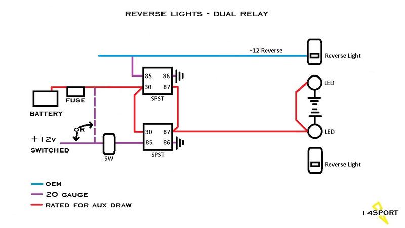
As shown, the switch controls the positive side of the control circuit. I personally prefer to switch the negative side but I know a lot of people prefer the positive side so that's how I drew it.
As a side note, I was fortunate enough to get a look at the factory wiring for the reverse lights and it appears the power wire for them runs from a relay in the TIPM all the way back to the lights. This means that tapping the reverse wire can be done anywhere along that path...at the tail lights, in the tub, or in the engine compartment. I did have another member tell me in a different thread that he traced the reverse wire from the tail light to the front of the tub and it was no longer 12v. Apparently, he was looking at the wrong wire.
It's comprised of simply two SPST relays. One triggered by the reverse circuit and the other triggered by a switch. As shown, the switch controls the positive side of the control circuit. I personally prefer to switch the negative side but I know a lot of people prefer the positive side so that's how I drew it.
As a side note, I was fortunate enough to get a look at the factory wiring for the reverse lights and it appears the power wire for them runs from a relay in the TIPM all the way back to the lights. This means that tapping the reverse wire can be done anywhere along that path...at the tail lights, in the tub, or in the engine compartment. I did have another member tell me in a different thread that he traced the reverse wire from the tail light to the front of the tub and it was no longer 12v. Apparently, he was looking at the wrong wire.
02-05-2015, 05:17 AM
#23
As I was running a 3 relay solution around my head, trying to map out how I was going to control two relays with a third, it made me realize that I was over-thinking the task at hand and the solution was actually quite simple. Not sure why I didn't think of this in the first place, but sometimes that's how the process goes. I present to you...the KISS schematic. It's comprised of simply two SPST relays. One triggered by the reverse circuit and the other triggered by a switch.
As shown, the switch controls the positive side of the control circuit. I personally prefer to switch the negative side but I know a lot of people prefer the positive side so that's how I drew it.
As a side note, I was fortunate enough to get a look at the factory wiring for the reverse lights and it appears the power wire for them runs from a relay in the TIPM all the way back to the lights. This means that tapping the reverse wire can be done anywhere along that path...at the tail lights, in the tub, or in the engine compartment. I did have another member tell me in a different thread that he traced the reverse wire from the tail light to the front of the tub and it was no longer 12v. Apparently, he was looking at the wrong wire.
It's comprised of simply two SPST relays. One triggered by the reverse circuit and the other triggered by a switch. As shown, the switch controls the positive side of the control circuit. I personally prefer to switch the negative side but I know a lot of people prefer the positive side so that's how I drew it.
As a side note, I was fortunate enough to get a look at the factory wiring for the reverse lights and it appears the power wire for them runs from a relay in the TIPM all the way back to the lights. This means that tapping the reverse wire can be done anywhere along that path...at the tail lights, in the tub, or in the engine compartment. I did have another member tell me in a different thread that he traced the reverse wire from the tail light to the front of the tub and it was no longer 12v. Apparently, he was looking at the wrong wire.
Not sure why I was so hell bent on putting a relay in place that actually fed power to the reverse lights (reverse lights hooked to pin 87). That absolutely looks like it will work, and no diode required. You're the man... thanks! 02-05-2015, 05:43 AM
#24
JK Junkie
Thread Starter
So you just tapped the reverse feed to activate the relay. Damn. That's so simple. Not sure why I was so hell bent on putting a relay in place that actually fed power to the reverse lights (reverse lights hooked to pin 87). That absolutely looks like it will work, and no diode required. You're the man... thanks!
Not sure why I was so hell bent on putting a relay in place that actually fed power to the reverse lights (reverse lights hooked to pin 87). That absolutely looks like it will work, and no diode required. You're the man... thanks!
If you really want to have fun start playing with the "aux fog lights turned on by stalk switch". That one's a beaut as it's a pwm wire.
02-05-2015, 06:49 PM
#25
kinda feel like the village idiot adding to this post...wow
with this new setup, with 2 spst relays, can I use the cordura switch? off/on? or on/off/on?
if you guys need therapy, there are 123 connective tissues, tendons/ligaments in the hand....lol
with this new setup, with 2 spst relays, can I use the cordura switch? off/on? or on/off/on?
if you guys need therapy, there are 123 connective tissues, tendons/ligaments in the hand....lol
02-05-2015, 08:38 PM
#26
I'll be testing this schematic out this weekend when installing my rear lights. I plan on using a rocker switch already installed in my a-pillar switch pod. I'll let you know if I run into any issues.
Last edited by smittycm; 02-05-2015 at 08:40 PM.
02-06-2015, 02:11 AM
#27
JK Junkie
Thread Starter

I know you had said you already had a SPDT relay. You can still use that if you want staying with the same pin numbers in the schematic. Pin 87a on the SPDT will be unused. It's always a good idea to cover up unused pins with an insulated female blade connector or tape.
You could use just about any style off/on switch... rocker or toggle are probably most suitable, but nothing to really stop you from using just about any switch you want depending on how you want to activate the lights. You could use a three way on/off/on switch if you really wanted to, but the second "on" position would be unnecessary. You could use that switch and even wire the second "on" position in, but it wouldn't be needed.
I'll be testing this schematic out this weekend when installing my rear lights. I plan on using a rocker switch already installed in my a-pillar switch pod. I'll let you know if I run into any issues.
I'll be testing this schematic out this weekend when installing my rear lights. I plan on using a rocker switch already installed in my a-pillar switch pod. I'll let you know if I run into any issues.
Run all the wires on the surface to make sure everything is okay before makin it pretty.
02-06-2015, 03:25 AM
#28
Thanks guys,
so far I have the spdt, spst, cheap Chinese light 16w, 4-LED, (that they didn't include a mounting bracket), a-pillar from rugged ridge, and 16 gauge wire. I want the switch to match dash lights green when off, and red when on. contura switch looks like the switch of choice.
You had said you would mount the relays in the brake light cavity. If I am reading your schematics correctly, wouldn't I have to run equal number of wires from front to back, regardless?
on a side note. I really want to learn how to post pictures, so I can do a proper write up!! I just soldered the "hidden garage door opener" mod, and was impressed. pics on phone, transfer to laptop, somehow get them to show up on this magic box...mystery...
keep up the info! Sounds like lots of guys are benefitting!
Last edited by dewey7015; 02-06-2015 at 03:35 AM.
02-06-2015, 04:16 AM
#29
JK Junkie
Thread Starter
You had said you would mount the relays in the brake light cavity. If I am reading your schematics correctly, wouldn't I have to run equal number of wires from front to back, regardless?
on a side note. I really want to learn how to post pictures, so I can do a proper write up!! I just soldered the "hidden garage door opener" mod, and was impressed. pics on phone, transfer to laptop, somehow get them to show up on this magic box...mystery...
keep up the info! Sounds like lots of guys are benefitting!
To post pics, don't use the quick reply. You have to be in the advanced editor and you will see Manage Attachments near the bottom. When you click that a dialogue box will open. Click add files then select files. Click on the files from your computer that you want and then click open and then upload files and then done.
Last edited by 14Sport; 02-06-2015 at 04:19 AM.
02-06-2015, 04:34 AM
#30
JK Junkie
Thread Starter
Also, Dewey, I'm not sure how much wiring experience your 123 connective tissues, tendons/ligaments have but to make the jumpers between the 30 pins and the 87 pins you can put two wires into one crimp and to tap the oem wire you can use a quick tap. These pics are from another thread I did but you can see how it is done.
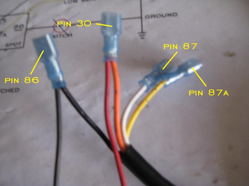

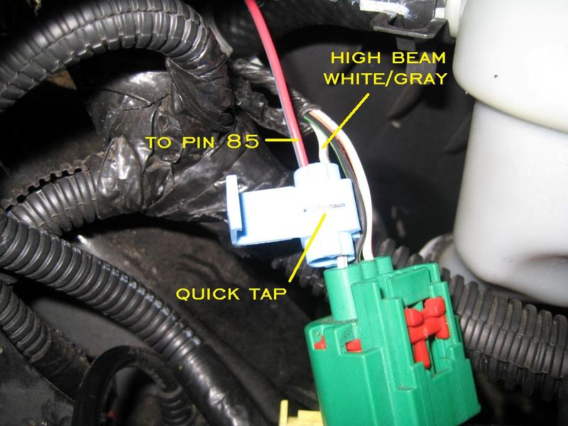
have but to make the jumpers between the 30 pins and the 87 pins you can put two wires into one crimp and to tap the oem wire you can use a quick tap. These pics are from another thread I did but you can see how it is done.Last edited by 14Sport; 02-06-2015 at 05:36 AM.