Wire connection question
 06-22-2015, 11:55 AM
#1
JK Newbie
Thread Starter
Join Date: Aug 2014
Posts: 12
Likes: 0
Received 0 Likes
on
0 Posts
After using a blue sea auxiliary fuse box and pre wiring relays in my jeep. I am ready to start adding some accessories and I'm a little confused on one aspect. In all the diagrams I see for wiring lights I see the hot wires from each light whether it be 2 lights or 4 lights all join together. and then a single wire connect to the relay. What is the proper way to join 2 or 4 wires together and come out with 1 wire. I'd prefer not to solder.
I assume the resulting single wire will need to be rated to handle the amperage of all the lights. My lights will most likely all be led's.
Thanks
I assume the resulting single wire will need to be rated to handle the amperage of all the lights. My lights will most likely all be led's.
Thanks
 06-22-2015, 12:13 PM
#2
JK Jedi Master


A terminal strip is one way ...
http://www.mouser.com/Search/m_Produ...7vEBoCh-rw_wcB
Maybe you could cobble one of these to the task ...
http://www.spectrowireandcable.com/p...+Way+Terminals
But I think soldering is a more elegant answer.
And, yes, whatever answer you use, including fusing and relay, will need to handle entire current load.
Last edited by Mark Doiron; 06-22-2015 at 12:17 PM.
06-22-2015, 01:02 PM
#3
JK Newbie
Thread Starter
Join Date: Aug 2014
Posts: 12
Likes: 0
Received 0 Likes
on
0 Posts
I like the idea of a terminal block, if I connected several pairs of lights to that and that had one wire going to a relay only the wire going to the relay would have to be sized for all the lights correct? Or do all the wires have to be sized for all the lights.
06-22-2015, 02:37 PM
#4
JK Junkie
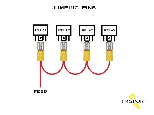
I do it like this usually. This shows relays but I do lights the same way because personally I'm not crazy about having open terminals that have power running through them.
Sometimes I will run one wire for each light to the sPOD and stack them on the connection or combine them in one crimp at the terminal.
Sometimes I will run one wire for each light to the sPOD and stack them on the connection or combine them in one crimp at the terminal.
06-22-2015, 04:20 PM
#6
JK Super Freak
Join Date: Mar 2010
Location: Ontario Canada
Posts: 1,182
Likes: 0
Received 0 Likes
on
0 Posts
Good advice posted I see.
Guess I'm old school...solder, heat shrink tube, wire loam, cable ties at equal intervals. (Broadcast Television Engineering will do that to a guy)
Multiple wires in a crimp, should be fine, you might need to size the crimp to accept x amount of cables based on their wire gauge I would suspect.
Guess I'm old school...solder, heat shrink tube, wire loam, cable ties at equal intervals. (Broadcast Television Engineering will do that to a guy)
Multiple wires in a crimp, should be fine, you might need to size the crimp to accept x amount of cables based on their wire gauge I would suspect.
Trending Topics
06-23-2015, 01:12 AM
#8
JK Newbie
Thread Starter
Join Date: Aug 2014
Posts: 12
Likes: 0
Received 0 Likes
on
0 Posts
P1TBU11. Check out this link http://www.bulkwire.com/wireresistance.asp it will tell you what size wire to use. Simply put in the total length of cable (including the length of ground wire) and enter amps (watts/voltage) and voltage.
06-23-2015, 01:12 AM
#9
JK Jedi Master
I'm not either. There are covers that can be used. Certainly, having a tool fall on the wrong place could be a real problem. Not much different than the battery, but I think most folks avoid placing loose tools around the battery area for that very reason. Having a new area could be inviting trouble.
06-23-2015, 01:20 AM
#10
JK Jedi Master
P1TBU11. Check out this link Wire Resistance and Voltage Drop Calculator it will tell you what size wire to use. Simply put in the total length of cable (including the length of ground wire) and enter amps (watts/voltage) and voltage.
So, in selecting your wire size, you should not only be concerned with current carrying capacity, but also with how much voltage drop you'll experience. The calculator Dave linked provides the "easier way" to do that engineering. FYI, it is certainly possible that vehicle LED light manufacturers engineer voltage regulators into the lighting assemblies to address this issue. And that may very well be the difference between the $1000 U.S.-made assemblies, and the cheap Chinese imports (besides the fact that I've witnessed those cheap Chinese imports vibrate apart when actually used off-road on rough terrain). I have no personal knowledge of this, but you may wish to investigate how well various assemblies perform at different voltage levels.