Wiring LED light bar to Daystar switches
 04-19-2016, 07:30 AM
#1
JK Newbie
Thread Starter

Join Date: Apr 2016
Location: Russell, PA
Posts: 13
Likes: 0
Received 0 Likes
on
0 Posts
Hey everyone,
This is my first post, as I've recently just bought myself a 2010 Wrangler! So after owning it for less than a week, I caught the plague that many of us seem to have and bought a seemingly endless amount of add-ons for the thing. One of which was a 50" light bar with two square pods for the A-pillars. To run the lights, I got a set of 4 Daystar rocker switches that I plan to mount onto the A-pillar on the interior. I just did something similar in my F-250 using the upfitter switches (which made things much easier) so I'd like to try and wire everything in a similar manner. I would like the light bar to be able to turn on/off independently using one switch, and have the light bar turn on/off with the high beams using another switch. Now bear with me and my lack of electrical knowledge but here is a brief explanation of how I plan to wire everything:
Connect my switches to the positive and negative of the driver side cigarette lighter so that the switches are only activated when the key is turned on.
Switch 1 for the lights: Run the positive from the lights directly to switch #1. Ground the lights in a fitting location. The lights should be live (once the key is turned on) for switch one after this, correct?
For switch 2: Use most of the wiring harness that came with the lights to hook up to the high beams. I plan to hook the + wire from the relay (#30) to the positive coming from switch #2. The second wire from the relay (#85) to a good ground. Third wire (#86) spiced into the high beam wire behind the drives side light. And lastly, the fourth wire from the relay (#87) to the positive on the lights. Spliced into what I already did for switch #1.
I have attached a rough sketch of my wiring plans to hopefully help clarify anything.

Now, after all that, my question is: will this work? I know a lot of people suggest using a SPDT switch but I like the look of the Daystar switches much better, plus it leaves me with the option to add more accessories down the road. Feel free to make any suggestions! Thanks in advance!
This is my first post, as I've recently just bought myself a 2010 Wrangler! So after owning it for less than a week, I caught the plague that many of us seem to have and bought a seemingly endless amount of add-ons for the thing. One of which was a 50" light bar with two square pods for the A-pillars. To run the lights, I got a set of 4 Daystar rocker switches that I plan to mount onto the A-pillar on the interior. I just did something similar in my F-250 using the upfitter switches (which made things much easier) so I'd like to try and wire everything in a similar manner. I would like the light bar to be able to turn on/off independently using one switch, and have the light bar turn on/off with the high beams using another switch. Now bear with me and my lack of electrical knowledge but here is a brief explanation of how I plan to wire everything:
Connect my switches to the positive and negative of the driver side cigarette lighter so that the switches are only activated when the key is turned on.
Switch 1 for the lights: Run the positive from the lights directly to switch #1. Ground the lights in a fitting location. The lights should be live (once the key is turned on) for switch one after this, correct?
For switch 2: Use most of the wiring harness that came with the lights to hook up to the high beams. I plan to hook the + wire from the relay (#30) to the positive coming from switch #2. The second wire from the relay (#85) to a good ground. Third wire (#86) spiced into the high beam wire behind the drives side light. And lastly, the fourth wire from the relay (#87) to the positive on the lights. Spliced into what I already did for switch #1.
I have attached a rough sketch of my wiring plans to hopefully help clarify anything.
Now, after all that, my question is: will this work? I know a lot of people suggest using a SPDT switch but I like the look of the Daystar switches much better, plus it leaves me with the option to add more accessories down the road. Feel free to make any suggestions! Thanks in advance!
 04-19-2016, 08:19 AM
#2
JK Junkie
There's no reason to run the load circuit through the switch when you have a relay.
I'm busy right now so I can't put a bunch of time into it at the moment but my initial thought would be as follows.
Pin 30 fused to battery.
Pin 87 to light positive.
Pin 86 to ground.
Pin 85 to light bar switch. Other side of switch to switched positive (cig lighter).
Then run a tap off the high beam to one side of the second switch with the other side of that switch going to pin 85 as well.
Couple of points.
You could use a 3 way switch (on/off/on) and do it with just one switch instead of two. Everything else would be the same.
My high beam feed is pwm. Not sure about yours. I use mine to trigger a garage door opener with no issues if that means anything. But PWM and relays don't always play well together.
I'm not familiar with the daystar switches but assuming they're regular toggles.
I suggest drawing it out and seeing if it makes sense to you as well.
Last edited by 14Sport; 04-19-2016 at 01:05 PM.
 04-19-2016, 10:56 AM
#4
JK Junkie
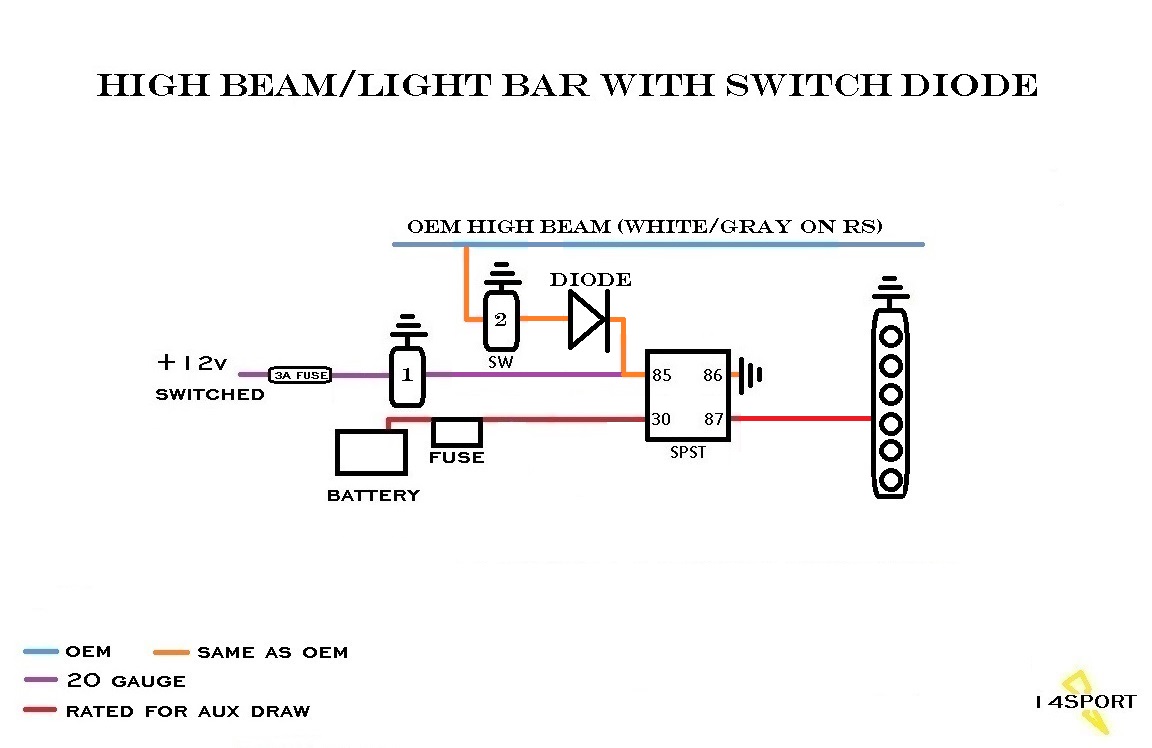
No the switches are wrong. I looked up the 3 pin daystar and it said the pins are
7 - ground
2 - power in
3 - power out.
So if that is what you have,
Switch 1 would be
7 - ground
2 - cig lighter positive
3 - out to pin 85
Switch 2 would be
7 - ground
2 - tap from high beam
3 - out to pin 85
When the switch is in the on position, it connects pin 2 to pin 3. So when you turn on switch one, the power coming from the cig lighter will go up to pin 85 on the relay and energize the coil which in turn activates the load circuit in the relay by connecting pin 30 to pin 87 which turns on the light bar. When switch one is off no power is being passed to the control circuit and the light bar is off. When switch two is in the on position, the high beam wire is now passed through the switch out to pin 85 on the relay. So whenever you hit the high beams, 12V should come though that switch and energize the control circuit on the relay. When the high beams are off, no power will come through and the light bar will be off. However, if you leave switch two on then turn on switch one, you will back feed the high beam unless you add a diode or use a 3 way switch which prevents that.
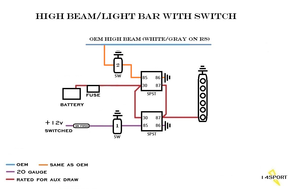
If you don't want to deal with a diode, you could use two relays instead. Mount them side by side. Jump the two pin 87s and two pin 30s together and then run a wire from either pin 87 to the light bar. Use switch one to feed pin 85 on relay one normally. Use switch two to link the high beam wire to pin 85 of relay two.
Like this...
7 - ground
2 - power in
3 - power out.
So if that is what you have,
Switch 1 would be
7 - ground
2 - cig lighter positive
3 - out to pin 85
Switch 2 would be
7 - ground
2 - tap from high beam
3 - out to pin 85
When the switch is in the on position, it connects pin 2 to pin 3. So when you turn on switch one, the power coming from the cig lighter will go up to pin 85 on the relay and energize the coil which in turn activates the load circuit in the relay by connecting pin 30 to pin 87 which turns on the light bar. When switch one is off no power is being passed to the control circuit and the light bar is off. When switch two is in the on position, the high beam wire is now passed through the switch out to pin 85 on the relay. So whenever you hit the high beams, 12V should come though that switch and energize the control circuit on the relay. When the high beams are off, no power will come through and the light bar will be off. However, if you leave switch two on then turn on switch one, you will back feed the high beam unless you add a diode or use a 3 way switch which prevents that.
If you don't want to deal with a diode, you could use two relays instead. Mount them side by side. Jump the two pin 87s and two pin 30s together and then run a wire from either pin 87 to the light bar. Use switch one to feed pin 85 on relay one normally. Use switch two to link the high beam wire to pin 85 of relay two.
Like this...
Last edited by 14Sport; 04-20-2016 at 03:28 AM.
04-20-2016, 06:46 AM
#6
JK Junkie
Glad to help, Zander. I suggest you run all the wires externally to test first. After everything is good, then snake them through. That's what I do. Good luck and looking forward to some pics.
04-20-2016, 06:49 AM
#7
JK Junkie
You want a diode sized large to handle the draw it will have upon it and the maximum voltage (13.8). In this case, it would be the draw of the oem high beam. I usually use relays. The one time I used a diode it was a 3A and worked fine but I can't remember what the draw was.
Last edited by 14Sport; 04-20-2016 at 07:21 AM.
Trending Topics
04-20-2016, 07:06 AM
#8
JK Junkie
Here's a 5A...
http://www.newark.com/nte-electronic...FUkkhgodSjADGg
...and a 10A.
http://www.amazon.com/Volt-Schottky-.../dp/B0056RHMCG
I just googled "diode 5 amp" and then "diode 10 amp".
Last edited by 14Sport; 04-20-2016 at 07:17 AM.
04-20-2016, 07:49 AM
#9
JK Junkie
 04-20-2016, 08:07 AM
#10
JK Newbie
Thread Starter
Join Date: Apr 2016
Location: Russell, PA
Posts: 13
Likes: 0
Received 0 Likes
on
0 Posts
