WxNerd2015's Never Ending Build -


 03-29-2017, 05:53 PM
#192
Super Moderator

If you're adding a tank with your OBA then go on ahead and change your oil now. I just added the viair 2 gallon tank with synergy brackets and it's not going to be fun to change the oil.
03-30-2017, 06:45 AM
#193
JK Enthusiast
Thread Starter
Thanks! I don't plan on adding a tank yet, and not sure if the small compressor, not the twin, is strong enough for it? Good to note though because I was thinking about it for a future upgrade! So thanks for the tip!
03-30-2017, 07:16 AM
#194
Super Moderator
I've got the Viair 400c and it'll air up tires, albeit slowly. Adding the tank allows you to continue to build pressure while you move between tires. The tank will let you break off 2-3 solid lug nuts with my 1/2" snap-on and it'll finish taking the wheel off with the compressor running. I'll be sticking to 3/8" air line all over. Instead of a fitting inside each door I'm going to do a port on the front and rear....along with one on the manifold to run air tools from under the hood.
03-30-2017, 07:43 AM
#195
JK Enthusiast
Thread Starter
I've got the Viair 400c and it'll air up tires, albeit slowly. Adding the tank allows you to continue to build pressure while you move between tires. The tank will let you break off 2-3 solid lug nuts with my 1/2" snap-on and it'll finish taking the wheel off with the compressor running. I'll be sticking to 3/8" air line all over. Instead of a fitting inside each door I'm going to do a port on the front and rear....along with one on the manifold to run air tools from under the hood.
03-30-2017, 08:12 AM
#196
JK Enthusiast
Thread Starter
To continue with the installations. I next had to remove the current CB setup that I had above the mirror. This required removing the visors, the GraBars, the Upper plastic corners on the windshield on the inside, as well as the upper piece along the top edge of the windshield. I ran the wiring down the passenger side and around for the CB, so as I pulled all that out, I removed pieces I needed for installation too. You can see in a previous post how the radio was installed, and I just reversed that down to the antenna wire.
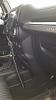
So with all those pieces removed, I moved to installing the CB Radio. First up was to route the antenna cable down the passenger side A-post and to the floorboard in the passenger side by removing the panel on the side of the dashboard. And with that off route the CB antenna cable into the glove box area and grab the controller box for the CB.
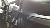
Plug the Antenna Cable in, and find a good spot to mount the controller box. For me, I mounted it on the bar just below the glove box through the glove box compartment. I will eventually go back and remount this a bit better, however for the mount, the zip ties are holding with no issue. And I could only find multicolored zip ties at the store, so this will definitely be some colorful wiring!
Once that is mounted, figure out where you want to run the power and ground wires (Red and Black wires) through the inside and how to get them power. For me, I am going to use the sPod for power, so I needed to get the power and ground into the engine compartment. So I started by routing the power and ground wires along the bottom edge of the passenger side speaker box and to the side of the dashboard. I then, with the side panel removed I found a route through the firewall and into the engine compartment as a foam filled hole in the upper portion of the opening.
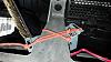
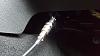
What is needed to get through this hole is to poke a hole with a screwdriver, coat hanger, or anything similar to make a hole for your wiring. When it's through, it will come out in this area of the engine compartment:
This was extremely difficult to get through, because there is a very small margin or error coming through this hole, and took me an hour and a half to get the right angle going through the hole to actually get it to come through the other side and not hit anything. But it is still one of the best spots if this is your method on this side. I then spliced on some more wire to get to the driver's side of the engine compartment, and ran it through the hole opening in the fender.

This location has held up pretty good so far, but you do need to be careful of the angle there and on a sharper metal edge. But for my purposes, I now have a hood lift kit which needs this hole, so I will have to rerun this wire. But once you have the power and ground through, I ran the wires across the firewall and connected to the sPod.
The last step here is attach the radio/mic itself. I ran the cable to connect the radio down out of the glove box compartment and underneath the dashboard. So just simply connect your radio to the connector and hang it on the mic mount installed in the previous step, and you are done! Just have to turn it on to check it and make sure all works!
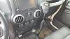
I am extremely pleased with this setup, and am very happy with the radio! Much more compact, in a better position, and I still get my weather radio that I love! I think the sound on it is plenty loud enough for me to hear it fine, and after 3 months at least of running it every time I am in the Jeep, it has worked quite well and had zero issues to me. Also, the reception is pretty good too! I am very happy as well to not have a radio hitting the rearview mirror and no concern of the button on the back falling and hitting the passenger, as the button broke on the other radio and had to improvise a washer et up there. Either way though, very happy with the new set up and highly recommend it!
So with all those pieces removed, I moved to installing the CB Radio. First up was to route the antenna cable down the passenger side A-post and to the floorboard in the passenger side by removing the panel on the side of the dashboard. And with that off route the CB antenna cable into the glove box area and grab the controller box for the CB.
Plug the Antenna Cable in, and find a good spot to mount the controller box. For me, I mounted it on the bar just below the glove box through the glove box compartment. I will eventually go back and remount this a bit better, however for the mount, the zip ties are holding with no issue. And I could only find multicolored zip ties at the store, so this will definitely be some colorful wiring!
Once that is mounted, figure out where you want to run the power and ground wires (Red and Black wires) through the inside and how to get them power. For me, I am going to use the sPod for power, so I needed to get the power and ground into the engine compartment. So I started by routing the power and ground wires along the bottom edge of the passenger side speaker box and to the side of the dashboard. I then, with the side panel removed I found a route through the firewall and into the engine compartment as a foam filled hole in the upper portion of the opening.
What is needed to get through this hole is to poke a hole with a screwdriver, coat hanger, or anything similar to make a hole for your wiring. When it's through, it will come out in this area of the engine compartment:
This was extremely difficult to get through, because there is a very small margin or error coming through this hole, and took me an hour and a half to get the right angle going through the hole to actually get it to come through the other side and not hit anything. But it is still one of the best spots if this is your method on this side. I then spliced on some more wire to get to the driver's side of the engine compartment, and ran it through the hole opening in the fender.
This location has held up pretty good so far, but you do need to be careful of the angle there and on a sharper metal edge. But for my purposes, I now have a hood lift kit which needs this hole, so I will have to rerun this wire. But once you have the power and ground through, I ran the wires across the firewall and connected to the sPod.
The last step here is attach the radio/mic itself. I ran the cable to connect the radio down out of the glove box compartment and underneath the dashboard. So just simply connect your radio to the connector and hang it on the mic mount installed in the previous step, and you are done! Just have to turn it on to check it and make sure all works!
I am extremely pleased with this setup, and am very happy with the radio! Much more compact, in a better position, and I still get my weather radio that I love! I think the sound on it is plenty loud enough for me to hear it fine, and after 3 months at least of running it every time I am in the Jeep, it has worked quite well and had zero issues to me. Also, the reception is pretty good too! I am very happy as well to not have a radio hitting the rearview mirror and no concern of the button on the back falling and hitting the passenger, as the button broke on the other radio and had to improvise a washer et up there. Either way though, very happy with the new set up and highly recommend it!
03-30-2017, 08:33 AM
#197
JK Enthusiast
Thread Starter
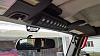
Next up was to add install the sPod switch bank, since most of those parts were already removed from uninstalling the CB. To do this, I needed to remove the footman loop and remove the CB bracket that was already installed there, and then place the bracket for the sPod switch pod up there and reattach the footman loop.
And the last step needed before starting to reinstall pieces is to hold the header piece up that goes along the top of the windshield and see where the bracket hits so you can take a small notch on either side out of the panel. This took me a few attempts to get the right amount off as I did not want to cut too much out, but once I got the right amount, the panel snapped back in with no problem.
With that mounted, attach the switch pod to the bracket using the 2 mounting screws, and then route the wire down the driver's side A Pillar, and through the hole in the firewall where the off road light' switch wire comes through. The grommet is up in the driver's side footwell, and it is empty. Just punch a hole through it and you can run your wire easy.
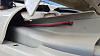
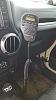
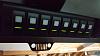
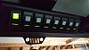
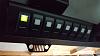
And lastly, button everything back up, reattach all bolts, accessories, and anything else disconnected, and the work in the cab is done! Here's a look at the switch panel installed:
And the last step needed before starting to reinstall pieces is to hold the header piece up that goes along the top of the windshield and see where the bracket hits so you can take a small notch on either side out of the panel. This took me a few attempts to get the right amount off as I did not want to cut too much out, but once I got the right amount, the panel snapped back in with no problem.
With that mounted, attach the switch pod to the bracket using the 2 mounting screws, and then route the wire down the driver's side A Pillar, and through the hole in the firewall where the off road light' switch wire comes through. The grommet is up in the driver's side footwell, and it is empty. Just punch a hole through it and you can run your wire easy.
And lastly, button everything back up, reattach all bolts, accessories, and anything else disconnected, and the work in the cab is done! Here's a look at the switch panel installed:
03-30-2017, 12:15 PM
#198
JK Enthusiast
Thread Starter
Now we will dive under the hood to get the rest of everything hooked up! First up was the sPod! Installation is pretty dang straight forward. The sPod is already on the bracket, and the power cables are already attached to the sPod, to simplify it even more.
First, I grabbed the sPod and mounted it up to the fender bolts. Just grab a 10 mm socket and loosen and remove 2 fender bolts. Once those are removed, line the bracket up on the fender, and reinsert the bolts in the fender and tighten it down.
The next step is to run the switch panel cord underneath the sPod along the fender, and up through the bottom on the side closest to the front and plug panel wire into the sPod (cord looks like an ethernet cable).
With that attached run the power cables back towards the firewall, along the fender, across the firewall (zip tying the wire up to the wiring harness that already exists there), and to the battery (10 mm socket to attach it to the negative and 12 mm socket to attach to the positive).
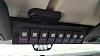
Once the power is connected, make sure you start the Jeep once to activate the sPod and then it's good to go! You can check this by going to the switch panel and check the lights on the switches, as well as taking a volt meter to each positive and negative connection in the sPod and check that the power is getting to those too. Here's some shots of the sPod switch panel working.
First, I grabbed the sPod and mounted it up to the fender bolts. Just grab a 10 mm socket and loosen and remove 2 fender bolts. Once those are removed, line the bracket up on the fender, and reinsert the bolts in the fender and tighten it down.
The next step is to run the switch panel cord underneath the sPod along the fender, and up through the bottom on the side closest to the front and plug panel wire into the sPod (cord looks like an ethernet cable).
With that attached run the power cables back towards the firewall, along the fender, across the firewall (zip tying the wire up to the wiring harness that already exists there), and to the battery (10 mm socket to attach it to the negative and 12 mm socket to attach to the positive).
Once the power is connected, make sure you start the Jeep once to activate the sPod and then it's good to go! You can check this by going to the switch panel and check the lights on the switches, as well as taking a volt meter to each positive and negative connection in the sPod and check that the power is getting to those too. Here's some shots of the sPod switch panel working.
03-30-2017, 12:58 PM
#199
JK Enthusiast
Thread Starter
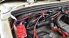
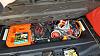
Lastly, I hooked up the air compressor. Most of the hook up for this I did outside the Jeep.
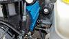
So first, I installed the 3 way splitter that came with the tire fill kit so I could attach the pressure cutoff switch as well as the quick chuck connector. You first have to pull out the plug on the side of the manifold, then add some pipe tape to the fittings before screwing them in. Then go ahead and do the same thing for the quick chuck connector and the pressure switch too.
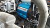
Next, attach the compressor to the bracket. I needed an extra set of hands to hold some of the screws in place while I started to tighten the nuts. It is much harder to attach those once the bracket is in the Jeep, but can be done there as well.
Next step was to get the compressor into the Jeep. So you need to find the brake booster in the driver's side part of the engine bay up on the firewall. Locate the 2 nuts on the brake booster, and remove both using a 12 mm wrench or socket. I used a ratcheting box wrench.
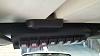
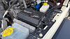
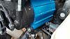
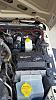
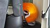
Go ahead and finagle the compressor and bracket on the studs for the brake booster, which will take some patients and work to get it in the proper position, but it will get there! And once the bracket is on the studs, go ahead and tighten the nuts back down to secure it.
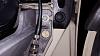
The compressor will look like this in the Jeep now:
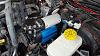
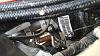
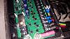
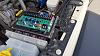
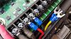
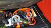
With the compressor mounted, the last step is to hook up all the electrical connections. I was attaching it to the sPod, so part of the wiring harness to the connector to the compressor was not needed, and just a small adapter was all that was needed in it's place. Attach the red and blue 90 degree connectors to the pressure switch, attach the group of 4 wires (red, black, green, and yellow) to the sPod adapter harness (if you weren't using an sPod or switch pros or trail rocker module, these 4 wires would be run through the firewall to a switch in the cab). Then attach the red and black ends of the sPod adapter to the sPod to the switch and ground spaces in the sPod. And for me, the green and yellow are just left off as I do not have air lockers to attach those to right now. And lastly, run the positive, negative, and ground cables from the compressor harness across the harness attached to the firewall over to the battery and connect them, along with mounting the ground on to one of the body ground mounts.
In the pictures below, you can see the connections for the CB and the Compressor to the sPod, and eventually I will transfer over the off road lights on to the sPod connection as well. But currently only the first two switches are used.
So first, I installed the 3 way splitter that came with the tire fill kit so I could attach the pressure cutoff switch as well as the quick chuck connector. You first have to pull out the plug on the side of the manifold, then add some pipe tape to the fittings before screwing them in. Then go ahead and do the same thing for the quick chuck connector and the pressure switch too.
Next, attach the compressor to the bracket. I needed an extra set of hands to hold some of the screws in place while I started to tighten the nuts. It is much harder to attach those once the bracket is in the Jeep, but can be done there as well.
Next step was to get the compressor into the Jeep. So you need to find the brake booster in the driver's side part of the engine bay up on the firewall. Locate the 2 nuts on the brake booster, and remove both using a 12 mm wrench or socket. I used a ratcheting box wrench.
Go ahead and finagle the compressor and bracket on the studs for the brake booster, which will take some patients and work to get it in the proper position, but it will get there! And once the bracket is on the studs, go ahead and tighten the nuts back down to secure it.
The compressor will look like this in the Jeep now:
With the compressor mounted, the last step is to hook up all the electrical connections. I was attaching it to the sPod, so part of the wiring harness to the connector to the compressor was not needed, and just a small adapter was all that was needed in it's place. Attach the red and blue 90 degree connectors to the pressure switch, attach the group of 4 wires (red, black, green, and yellow) to the sPod adapter harness (if you weren't using an sPod or switch pros or trail rocker module, these 4 wires would be run through the firewall to a switch in the cab). Then attach the red and black ends of the sPod adapter to the sPod to the switch and ground spaces in the sPod. And for me, the green and yellow are just left off as I do not have air lockers to attach those to right now. And lastly, run the positive, negative, and ground cables from the compressor harness across the harness attached to the firewall over to the battery and connect them, along with mounting the ground on to one of the body ground mounts.
In the pictures below, you can see the connections for the CB and the Compressor to the sPod, and eventually I will transfer over the off road lights on to the sPod connection as well. But currently only the first two switches are used.
03-30-2017, 01:09 PM
#200
JK Enthusiast
Thread Starter
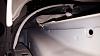
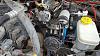
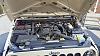
And here's shots of the final view of the engine compartment with everything installed:
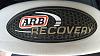
Additionally, I also redid where some of my extras in the Jeep are stored. I got a snatch strap, and that is stored up next to the roll bar in the back. And I also took out the small portable air compressor and gave that to my fiance and placed all the air house line and fittings in the back under the floor.
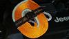
Also, I would like to apologize for the lack of pictures at some points, as well as the less than par writeups for some of these installs, but I know there are already some very good writeups for these installs, and it was done in so many parts for me, that I got going and completely forgot to fully document. If you have any questions, or there are things that I missed, please ask or let me know!
Additionally, I also redid where some of my extras in the Jeep are stored. I got a snatch strap, and that is stored up next to the roll bar in the back. And I also took out the small portable air compressor and gave that to my fiance and placed all the air house line and fittings in the back under the floor.
Also, I would like to apologize for the lack of pictures at some points, as well as the less than par writeups for some of these installs, but I know there are already some very good writeups for these installs, and it was done in so many parts for me, that I got going and completely forgot to fully document. If you have any questions, or there are things that I missed, please ask or let me know!