DIY Auxiliary Fuse Block & Box
 12-01-2012, 03:12 PM
#21
JK Jedi Master
Ya Ron. I don't claim to understand why automotive manufacturers install electrical circuits without a fuse. But I also don't understand how the distance of a conductor would protect it from a short circuit? I remember reading about some strange properties where a short may occur on a generator circuit. But I can't remember where I seen it.
The lead to the TIPM is an example. It's close to the battery, and the lead is not near anything to short against.
Our alternator has a fuseable link. Maybe because it leaves the battery and disappears in a bundle on it's non-direct route to the alternator.

 12-24-2012, 01:26 PM
#26
JK Enthusiast
Join Date: Mar 2010
Location: st. louis, MO
Posts: 363
Likes: 0
Received 0 Likes
on
0 Posts
Great Job BlueBruin!! I know absolutly ziltch when it comes to auto wiring. I can wire just about anything in a house but for some reason auto has always stumped me. But with your great and easy to follow pictures, I now have the confidence to make one myself.
12-26-2012, 11:27 AM
#27
JK Freak
I mounted two blue seas on an s pod bracket on a piece of aluminum. One is constant, one is switched. I used a power distribution block mounted to the TIPM to splice the 8 gauge. Also fused both of those runs. Used an inline relay and pulled switched power from it out of the TIPM. I wished I had used all black wiring, to make it look cleaner; I'm going to put it all in flex loom. Now I have 6 switched and 6 constant circuits. Blue wires are ground, red are 12v. Relay is tucked next to battery. Will look a lot cleaner in flex loom.
01-05-2013, 03:18 PM
#28
JK Newbie

Join Date: Mar 2012
Location: Denham springs
Posts: 24
Likes: 0
Received 0 Likes
on
0 Posts
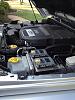
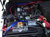
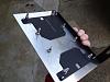
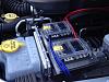
I mounted two blue seas on an s pod bracket on a piece of aluminum. One is constant, one is switched. I used a power distribution block mounted to the TIPM to splice the 8 gauge. Also fused both of those runs. Used an inline relay and pulled switched power from it out of the TIPM. I wished I had used all black wiring, to make it look cleaner; I'm going to put it all in flex loom. Now I have 6 switched and 6 constant circuits. Blue wires are ground, red are 12v. Relay is tucked next to battery. Will look a lot cleaner in flex loom.
Attachment 401992
Attachment 401993
Attachment 401994
Attachment 401995
Attachment 401992
Attachment 401993
Attachment 401994
Attachment 401995
01-06-2013, 04:37 PM
#29
JK Enthusiast
I just found this thread. First thing I noticed was the long lead of wire to the other side of the engine bay that wasn't protected as a few have noticed. However even if the box was mounted near the battery there should be a fuse or breaker protecting the short piece of wire as well as any fuse bus it terminates to.
The blue sea fused distribution blocks look nice. I was thinking about mounting one behind the glove compartment or maybe in the engine bay. However I've been taking a look at the sPOD. It's costly, but after adding up all the components I would like to have to put together a fused dist. block, with several relays being controlled by Contoura switches in a switch pod with wire and all the other little things, my material is almost 3/4 the price of the sPOD.
Plus all the labor to put it together. Although I love that part and would feel kind of cheated having someone else do most of the connections for me.
01-06-2013, 04:57 PM
#30
JK Enthusiast
If you used a fuse block such as the blue sea than you would usually use relays in series with the power coming from the block to your accessory (lights,etc.). This relay would be controlled by a switch that gets it's power from an accessory 12V circuit that is on when the Jeep is on and that in turn cuts power to your accessories when the vehicle is off.
There are a few different ways to ensure your accessories don't drain your battery.
The way sPOD is set up, won't allow you to have switches that have dual l.e.d's, one when the switches are powered and another when the load is turned on. I like this dual l.e.d option, but that's just me, I'm still contemplating what would be best.
From what I can tell, you could just put their switch power lead on a relay controlled by a switched 12V circuit which cuts power to the switches and relay control circuit when the vehicle is off. Than just add a dual l.e.d. switch and an extra ground.
*Another thing, although 50 amp max for this power distribution is probably enough for most of the stuff I would run off of it. I'm not sure I would want to limit myself. After 4 lighting accessories I plan to do would be about 30-35 amps. Not sure if the other (unknown) two would fall in under 15 amps total, plus I don't like to max my circuit to more than 80% of the fuse / breaker rating anyway. That's just me being NEC conscious.
Last edited by kaffeene; 01-06-2013 at 05:51 PM.