DIY Spod on the super cheap!
 03-14-2015, 08:22 PM
#1
JK Enthusiast
Thread Starter
Alright so I finely get to give back to the community... Now to be quite honest and franks with you this isn't completely done just yet... I have switches but no lights, winch, cb, ect. Just going to break it down to the simplest form I can. Also I have had a couple of beers throughout the process and I will be switching from my computer to my phone (to upload pictures). Bare with me here I should be able to some beginning electricians on the right track. Of course a disclaimer (my lawyer made me do this), if you attempt this mod I am not liable for anything completely bricked!!!!!!
What I have used so far and the approximate price.
1 Plano waterproof box, around $9
4 each 30amp 4 prong relays around $7 a piece
1 fuse panel (6 fuses) got it from auto zone, forgot the price... under $15 for sure...
1 8 position terminal block super cheap from radio shack (going out of business sale)
1 box of insulated 16-14 gauge female disconnects. less than $5
1 roll of 16 gauge wire 35' worth. not sure on the price
1 roll of 18 gauge wire 35' worth, had it from previous project
1 box of terminal connectors again had it from a previous project
Alright so on the Plano tackle box I cut out the dividers with my el cheapo HF dremel tool see pictures below
 03-14-2015, 08:33 PM
#4
JK Enthusiast
Thread Starter
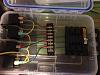
Alright, so on prong 58 of the relay that is your ground. Feel free to wire each one to each relay in a daisy chain. At the end relay I gave myself about 9 inches of wire with a female snap connector at the end. When I find a spot for the box I will wire the ground and connect a male snap connector to it... and snap it together. Crazy right? See pics below.
Trending Topics
03-14-2015, 08:39 PM
#8
JK Enthusiast
Thread Starter
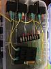
Next I wired in the wires for the switches, i used the 18 gauge for this. One end will be connected to prong number 86, the other will go to the terminal block
03-14-2015, 08:42 PM
#9
JK Enthusiast
Thread Starter
I know what you are thinking, alright chemlight_ninja, how do I get juice to my accessories, well hold your horses. You're going to need a couple of female connectors to your 16 gauge wire. So from prong 30 you will want to connect that to your fuse box. See below
03-14-2015, 08:45 PM
#10
JK Enthusiast
Thread Starter
Still no juice to the accessories? Well you're pretty close to done... Take your 16 gauge with connectors from prong 87 to the other open spots on your terminal block. Like so
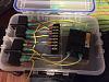
And your done... Ish.
And your done... Ish.