DIY Spod- Waytekwire
 08-15-2015, 09:30 PM
#11
JK Enthusiast
Thread Starter
Join Date: Jan 2015
Location: Des Moines
Posts: 111
Likes: 0
Received 0 Likes
on
0 Posts
Ground locations- the accessory you are running should be grounded as close to the accessory as possible, no need to run the ground back to cooper relay panel. Under the hood, there are factory ground bolts on the inside of the fenders on both sides (hard to see in this pic)
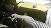
And at the kick panel area
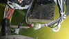
And at the kick panel area
 08-17-2015, 04:29 AM
#12
JK Enthusiast
Join Date: Mar 2012
Location: springboro, ohio
Posts: 162
Likes: 0
Received 0 Likes
on
0 Posts
I started a thread on this a year and a half ago on a different forum, but figured i would share it here, for anyone interested in building one.
Big thanks to White Dynamite for giving me the idea to use the Cooper Bussman relay/fuse panel.
The proper way of hooking up electrical accessories simply involves a switch, relay, fuse and wiring. That's all there is to it. This writeup will show you an easy way to wire up 5 circuits and avoid a lot of unnecessary wiring by using the Cooper Bussman relay/ fuse panel. Instead of wiring up 5 relays individually- you only need to supply the hot lead from the fuse to the relay, and the input/output wires to each relay.
This writeup utilizes 30 Amp relays- which is enough to run a 50" LED light bar, or most electric air compressors.
You should verify before hand, what circuits you already have and how many amps they will require- For LED lights- Add up total wattage of each light- (Total Watts/12volts=Amps Required)- Example- 100 watts/12= 8.33 Amps
This write up is for a simple 5 switched accessory circuit. If you need more than 5 accessories, you will need an additional relay/fuse panel and additional relays- or will up individual relays as needed. Cooper Bussman makes a 10 relay panel with 20 fuses. http://www.waytekwire.com/item/46354...-2-88-MM-DUAL/
Please read through the whole writeup twice before ordering anything….
This circuit passes 12 volts through the switch to the relay and then provides 12 volts out to the positive on the accessory. The accessory is then grounded to complete the circuit.
This circuit is Live all the time, regardless of ignition switch. You can install a “kill” switch on the power wire supplying 12 volts to the switches or run that wire off a 12 volt switched power wire. You can run a tap to the factory fuse panel for a switched source.
A Single Pole Single Throw switch of almost any type can be used. I chose Carling Rocker switches for this writeup.
You are free to decide where you want your switches, and where you want to mount the relay panel. It can be mounted under the hood, and has a waterproof cover included. You would want to plug any unused holes in the bottom of the panel. They sell plugs for the unused spots in the relay panel, i used extra seals and some silicone to waterproof mine.
if you want to mount it under the hood, there are brackets available- B028-7012-0-J $4.35 from waytekwire
A perfect switch mount for those with an automatic is Daystar’s KJ71034bk ($20) as it has 5 switch locations. The Daystar switch mount could be easily modified to mount to the upper windshield or anywhere.
Tools Required- wire cutters, wire strippers, wire crimpers, soldering gun, dremel or cutting tool (depending on where you mount your switches)
All parts listed are from waytekwire.com (unless otherwise noted)- there is a minimum order quantity on the smaller items.
Here's the parts for the relay panel
<img src="https://www.jk-forum.com/forums/attachment.php?attachmentid=619576"/>
and here are the switches
<img src="https://www.jk-forum.com/forums/attachment.php?attachmentid=619577"/>
The required components are:
46343 Relay/Fuse Panel $28.48
75730 Relays $14.55- Qty 5
31068 280 series Terminals (14-16ga) $5.84- Qty 50
39001 Terminal Seals $6.34- Qty 100
31713 Blue Female Quick Disconnect terminals $8.49- qty 50
46923 80 Amp Circuit Breaker $24.71
$88.41 + fuses, switches and wiring.
Depending on what you are hooking up, will determine what size fuses you use. You can go to any auto parts store to get the fuses as well in smaller quantites.
Most electric compressors will be 20-30 Amps, some higher. These relays are only rated at 30 Amp, and the mini style fuses only go to 30 Amp.
A few examples-
A 50" LED lightbar (288 watt) will draw 24 Amps.
Two windshield mount LED spotlights- 30 watts each = 5 amps total.
12 – 10 watt led rock lights = 10 Amps total.
You can fuse slightly higher than your expected total load per channel.
Mini Fuses or Circuit Breakers-
From waytekwire, fuses are:
46257 20A Fuses $5.60- Qty 50
46255 10A Fuses $5.60- Qty 50
Waytek has mini circuit breakers you can get instead of fuses.
46864- 25A Mini Circuit Breaker $6.84 (qty 3)
46862- 15A Mini Circuit Breaker $6.84 (qty 3)
Switch examples-
Typical Carling Rocker Switches from waytekwire- light turns on only when switch is on.
44305 SPST Rocker Body Lighted $4.24ea- qty 5- $21.20
44352 Rocker Cover Red Lense $1.38ea- qty 5- $6.90- don't order these if you will get otrattw covers
Otrattw has dual lit led switch bodys ($10 each) and even have some with two different colored led’s. So one led can turn on when you turn the headlights on (illumination) and one led will turn on when the switch is activated.
OTRATTW :: Switch Body :: SPST ON/OFF :: Upper Independent Light
Wiring- Go to a local Car Audio Shop. You will need some 8 gauge wire for positive and ground, and then install the 80 Amp circuit breaker less than 12" from the battery positive post.
You will also need some 16 gauge wire to run from the relay panel to the switches- 7 conductors (1 for each switch, and one for 12volt feed from fuse 6, and 1 to bring the ground from the switches back to the ground terminal on the relay panel) Use automotive primary wire. Do not use speaker wire under the hood as the temperature rating on the wire is not high enough.
You will also want 16 gauge wire to run from the outputs of the relay panel to your accessories.
Misc- (4) 8ga ring terminals, (1) Blue (16ga) ring terminal, (5) Blue Male Fully Insulated .250 Quick Disconnects- Car audio store
About $35 for wiring, terminals
You can get the Covers in a lot of different colors and lense colors from waytekwire or you can get the printed specific covers from otrattw.com for $5 each, ie “Rock Lights, Beer, etc”
Before you begin, please note, once you insert the terminal into the back of the relay panel, it is pretty much permanent, so make sure your crimp on the terminal is good, solder it if you can.
** Test each crimp job by holding the terminal and pulling on the wire to see if it comes loose from the terminal.
Waytek has a terminal removal tool- if you need it. $9.46
Delphi 12094429 Metri-Pack Terminal Removal Tool for 150, 280, GT150, GT250 Series
Waytek also has a crimp tool for the terminals- I just used pliers to bend over the tabs and soldered it, but you could buy the crimp tool and get by without soldering. (at the time I did this writeup, I only knew of one crimper that was $84, but now there is one that is $23.28)
CrimpTool for 22-14 GA Delphi Metri-Pack 150, 280 & Weather-Pack Terminals
You will want to make all the connections to the back of the relay panel before installing the fuses or relays. If you will not be adding an accessory yet for all of the channels, don’t install the relay or fuse for the unused channel.
I ran a short pigtail with quick disconnects as my main output from the relay panel. This way, for every accessory I hooked up, I could ground the accessory close to the accessory, only run a positive wire from the accessory to the relay panel. That way the accessories can be disconnected or connected easily.
typical wire crimped (I did not have the actual crimp tool) to terminal (slide seal on before crimping) and solder the crimp.
<img src="https://www.jk-forum.com/forums/attachment.php?attachmentid=619579"/>
The back of the relay panel, terminal posts on the bottom- The left post on the back goes directly to the positive on the battery with a fuse holder – 8 gauge wire. This post and connection will need to be taped up completely so it does not get grounded out.
The right side post on the back goes to ground.
<img src="https://www.jk-forum.com/forums/attachment.php?attachmentid=619580"/>
How the terminals go into the relay panel (note orientation of terminal in the hole)
<img src="https://www.jk-forum.com/forums/attachment.php?attachmentid=619581"/>

 subscribed!
09-17-2015, 06:24 PM
subscribed!
09-17-2015, 06:24 PM
#19
JK Enthusiast
Join Date: Feb 2013
Location: Oakland, CA
Posts: 255
Likes: 0
Received 0 Likes
on
0 Posts
I will have to post in three post to send you the pictures the app is being weird when I try to post more the one photo.
Post one the switches on driver "a" pillar
Post one the switches on driver "a" pillar