Rubicon Off-Road switch panel modification
 04-16-2016, 04:27 PM
#1
JK Newbie
Thread Starter

Hey guys, I'd like to start off by saying that I've been leeching off of jeep forums and have made no real contributions to the community yet so I figured I'd start here! Also sorry if a thread for this already exists! I looked and all I could find was people trying to figure out how to modify the oem switch panel under the AC controls(the one that contains the hazard button).
This was done on a 2016 JKU Rubicon
That being said, Here's Some Pictures!
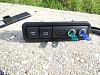
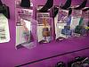
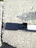
Note: I'm not a fan of the switches I used, but they were the only ones that I found that would fit in the switch panel. I picked them up at the local auto store. Also, the ring that they came with to screw the switch on so it stays in place was too thick so I used the thinner metal ring from another switch that I had from my last jeep. The metal ring also makes the switches not look so cheap. If you're really careful and precise it looks as though you can fit 4-5 switches on this panel. Might disturb the integrity of the plastic though. I've also thought about cutting out the off-road part and putting in a piece of metal/plastic cut to the right size. The way the off-road panel bows out really limited my choice of switches.
Materials used:
Steps(Sorry for lack of pictures, they were sort of an after thought):
1. Pry off the driver's side door jam panel (Refer to this if having trouble)
1.5(optional) Remove driver's side door or unhook wiring so the door will swing open all the way, this makes it easier to get your hands in that small space.
2. Remove the switch panel by squeezing the metal brackets and pushing out lightly. There are 4 of them, 2 on top and 2 on bottom. You might want to try using the screwdriver or knife to press in the top right one, that one gave me a hard time.
3. Unplug panel so that it can be taken to a workstation (in my case i worked on the brick wall in my driveway)
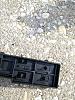
4. Remove the back panel of the switch. You will see that there are small ridges that hold the backing of that switch panel on. Use the knife/screwdriver near each of those ridges to pry the backing plate off. I found it easier to pop the bottom ones out first and then you can work the top ones out. BE CAREFUL that nothing breaks loose and the computer chip inside the panel comes flying out or the pins on the factory wire plug get bent.
5. Carefully remove the factory circuit board, it just lifts right out. Place it carefully somewhere where it will not get damaged.
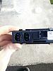
6. You can now drill holes in the "OFF-ROAD" portion of the switch panel! I drilled from the inside -> out. Make sure your switches will all the way down in the panel before drilling! The open portion of the panel is wider than the bottom opening (I broke a switch trying to make the ones I already had fit).
7. Once you have your holes drilled and you've made sure your switches all fit, you're ready to now drill out the back panel! The panel backing had a sticker on it and I needed to drill right where it was, So I moved it to the other side of the factory wiring plug housing.
8. Mark up the places that you need to drill so that you may stick the switch connectors through the back of the panel to plug into your switches. This hold doesn't need to be too big, just large enough to fit the dremel in there so we can make the hole a good oval/rectangle shape.
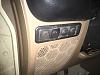
9. Once All the holes are drilled, install your switches into the holes you've drilled on the panel, snap on the back cover, and plug some wires into it! You want to plug the wires in before you snap the panel back into place though, they will be almost impossible to get to. Just make sure you pass the wires through the hole for the switch panel first... I made that mistake but it was no big deal.
Let me know if you have any questions or need any clarifications! I'll be popping it open again tomorrow to wire another set of lights (I only wired up one of those switches so far). I'll try to take more pictures!
This was done on a 2016 JKU Rubicon
That being said, Here's Some Pictures!
Note: I'm not a fan of the switches I used, but they were the only ones that I found that would fit in the switch panel. I picked them up at the local auto store. Also, the ring that they came with to screw the switch on so it stays in place was too thick so I used the thinner metal ring from another switch that I had from my last jeep. The metal ring also makes the switches not look so cheap. If you're really careful and precise it looks as though you can fit 4-5 switches on this panel. Might disturb the integrity of the plastic though. I've also thought about cutting out the off-road part and putting in a piece of metal/plastic cut to the right size. The way the off-road panel bows out really limited my choice of switches.
Materials used:
- dremel
- drill
- knife/screwdriver - to pry off the the panel by the driver side door jam
- switches
Steps(Sorry for lack of pictures, they were sort of an after thought):
1. Pry off the driver's side door jam panel (Refer to this if having trouble)
1.5(optional) Remove driver's side door or unhook wiring so the door will swing open all the way, this makes it easier to get your hands in that small space.
2. Remove the switch panel by squeezing the metal brackets and pushing out lightly. There are 4 of them, 2 on top and 2 on bottom. You might want to try using the screwdriver or knife to press in the top right one, that one gave me a hard time.
3. Unplug panel so that it can be taken to a workstation (in my case i worked on the brick wall in my driveway)
4. Remove the back panel of the switch. You will see that there are small ridges that hold the backing of that switch panel on. Use the knife/screwdriver near each of those ridges to pry the backing plate off. I found it easier to pop the bottom ones out first and then you can work the top ones out. BE CAREFUL that nothing breaks loose and the computer chip inside the panel comes flying out or the pins on the factory wire plug get bent.
5. Carefully remove the factory circuit board, it just lifts right out. Place it carefully somewhere where it will not get damaged.
6. You can now drill holes in the "OFF-ROAD" portion of the switch panel! I drilled from the inside -> out. Make sure your switches will all the way down in the panel before drilling! The open portion of the panel is wider than the bottom opening (I broke a switch trying to make the ones I already had fit).
7. Once you have your holes drilled and you've made sure your switches all fit, you're ready to now drill out the back panel! The panel backing had a sticker on it and I needed to drill right where it was, So I moved it to the other side of the factory wiring plug housing.
8. Mark up the places that you need to drill so that you may stick the switch connectors through the back of the panel to plug into your switches. This hold doesn't need to be too big, just large enough to fit the dremel in there so we can make the hole a good oval/rectangle shape.
9. Once All the holes are drilled, install your switches into the holes you've drilled on the panel, snap on the back cover, and plug some wires into it! You want to plug the wires in before you snap the panel back into place though, they will be almost impossible to get to. Just make sure you pass the wires through the hole for the switch panel first... I made that mistake but it was no big deal.
Let me know if you have any questions or need any clarifications! I'll be popping it open again tomorrow to wire another set of lights (I only wired up one of those switches so far). I'll try to take more pictures!

The following users liked this post:
bachuus (01-10-2020)
04-16-2016, 06:09 PM
#2
Super Moderator

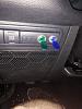
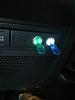
I just got rid of the locker switches that jeep used (so that I could turn my lockers on and off when I want). I used the original panel for a safety switch for the new locker switches and then the rest of the switches are for rock lights and such.
04-16-2016, 06:40 PM
#3
JK Newbie
Thread Starter
Ah nice, I like it! Those switches are powering aftermarket lockers right? I was also looking into designing something that could be 3d printed but my printer can't print ABS and PLA gets too melty when it gets too hot!
04-16-2016, 06:45 PM
#4
Super Moderator
3D printed would be cool!
03-27-2020, 05:22 PM
#5
[QUOTE=jedg;4208140]I just got rid of the locker switches that jeep used (so that I could turn my lockers on and off when I want). I used the original panel for a safety switch for the new locker switches and then the rest of the switches are for rock lights and such.
Attachment 644022
Mind telling me what you did with the factory wiring harness that runs here? I recently did the same thing to better control my lockers, but now I don�t have my steering wheel controls and what not. Curious if you had a similar issue
Attachment 644022
Mind telling me what you did with the factory wiring harness that runs here? I recently did the same thing to better control my lockers, but now I don�t have my steering wheel controls and what not. Curious if you had a similar issue

