
Wiring a Harley Garage Door Opener into 2014 JK Write-up
 01-03-2015, 12:09 PM
#1
JK Junkie
Thread Starter
I removed a Harley Davidson garage door transmitter from a bike I'm planning to sell. After seeing it sitting on my workbench for a few days, I decided I would install it in my JK. Harley Davidson garage door openers consist of a receiver mounted inside your garage and wired to your garage pushbutton. Then a transmitter is installed on your bike and is activated by turning your high beam on then off quickly. You can buy additional transmitters for each bike (or JK for that matter) and all will use the same receiver. The transmitter has four wires which I labelled while removing it: high beam, low beam, +12V switched, and ground. Seemed like a pretty easy install.
The first thing I did was bench test the transmitter using a 12V transformer. What I discovered was that when the high beam is hit on a Harley the low beam cuts out. On my JK the low beam stays on with the high beam. So much for a four wire install. So I figured the best way to accomplish the low/high/low quick switch on my JK would be to use a Single-Pole Double-Throw (SPDT) relay. I tested this on the bench and it worked. My first iteration was to use a momentary switch to activate the sequence, but I really wasn't too keen on mounting it on my dash. Further thought made me want to use the flash-to-pass circuit on the JK. I tested it on the JK and it worked. So on to the install.
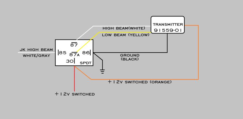
First the schematic:
Pic 1: Putting the low beam on pin 87a and the high beam on pin 87 allows a rapid transition of the two circuits. All I would need to do is send a quick pulse to pin 85. I used a switched power source so it could only be activated with the key in the run position. Hey it's a soft top.
Pic 2: This is what I was working with, a transmitter and a SPDT relay. I will mount them side-by-side near the battery making for less wiring.

Pic 3: Since I needed a ground and 12V switched for both the transmitter and the relay, I combined the two into one female spade connector for both ground and 12V.
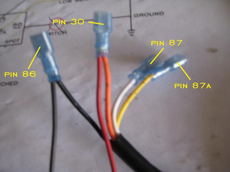
Pic 4: This is how it looked when connected to the relay. I left about 6' of both power and ground so I would have plenty of wire to work with. The only open pin at this point was pin 85, the 12V trigger for the control circuit, which will be wired into the passenger side high beam wire and activated by the flash-to-pass switch.

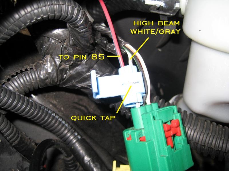
Pic 5: I pulled the grill and passenger head light and used a quick tap on the white/gray wire. I believe the driver side high beam wire is white/light green if you're so inclined. This picture was actually taken while testing so the quick tap is not closed or taped up yet.
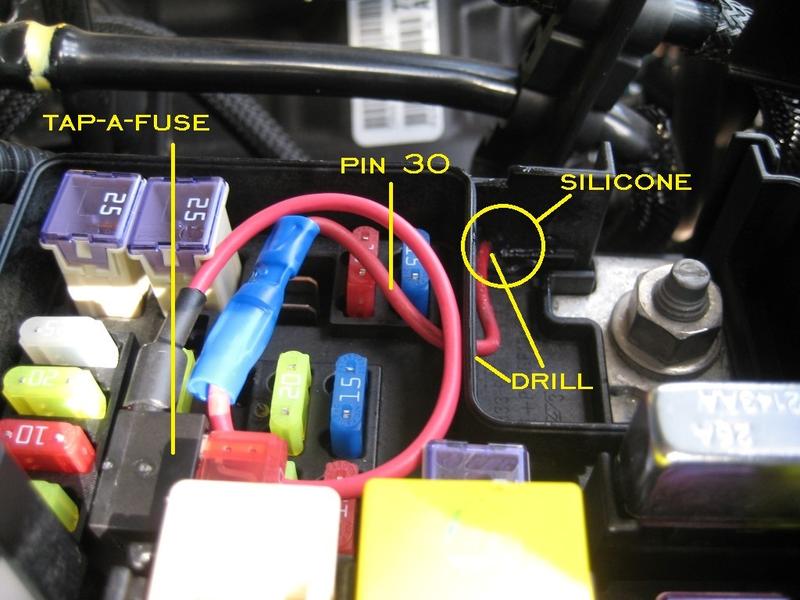
Post 3, pic 1: For the 12V switched power, I used an add-a-circuit (tap-a-fuse) in an empty location in the TIPM following ronjenx's excellent write-up here. To find one, I tested the open slots with my multimeter to see which didn't have power. I then moved the key to the run position and tested them again, letting me know which were switched. I chose that particular slot because the add-a-circuit with the upper fuse in it fit nicely. I then drilled small holes just big enough to run the wire through to get outside the box. Finally, I added a dab of silicone to seal it up tight as Ron suggests.
Post 3, pic 2: This is how it looked after the TIPM lid was closed.

Post 3, pic 3: Next up, I ran the ground wire to the battery negative post...

Post 3, pic 4: slapped some 3M automotive double-backed tape on the transmitter...

Post 3, pic 5: mounted it beside the battery and used a self-tapping screw to mount the relay next to it. I mounted it up high to get better range on the transmitter with less interference.

Then I did a test run, re-installed the head light, and re-installed the grill. It activated just fine while I was backed into my driveway. No more clickers.
The install overall was quite easy, especially if you have any experience with wiring. Overall I would allow 3 to 4 hours for install. I know this is a very specific application and probably won't be done by anyone else. However, it's good to know that you can.
If the pics aren't showing up for you the rest are in post 3.
The first thing I did was bench test the transmitter using a 12V transformer. What I discovered was that when the high beam is hit on a Harley the low beam cuts out. On my JK the low beam stays on with the high beam. So much for a four wire install. So I figured the best way to accomplish the low/high/low quick switch on my JK would be to use a Single-Pole Double-Throw (SPDT) relay. I tested this on the bench and it worked. My first iteration was to use a momentary switch to activate the sequence, but I really wasn't too keen on mounting it on my dash. Further thought made me want to use the flash-to-pass circuit on the JK. I tested it on the JK and it worked. So on to the install.
First the schematic:
Pic 1: Putting the low beam on pin 87a and the high beam on pin 87 allows a rapid transition of the two circuits. All I would need to do is send a quick pulse to pin 85. I used a switched power source so it could only be activated with the key in the run position. Hey it's a soft top.
Pic 2: This is what I was working with, a transmitter and a SPDT relay. I will mount them side-by-side near the battery making for less wiring.
Pic 3: Since I needed a ground and 12V switched for both the transmitter and the relay, I combined the two into one female spade connector for both ground and 12V.
Pic 4: This is how it looked when connected to the relay. I left about 6' of both power and ground so I would have plenty of wire to work with. The only open pin at this point was pin 85, the 12V trigger for the control circuit, which will be wired into the passenger side high beam wire and activated by the flash-to-pass switch.
Pic 5: I pulled the grill and passenger head light and used a quick tap on the white/gray wire. I believe the driver side high beam wire is white/light green if you're so inclined. This picture was actually taken while testing so the quick tap is not closed or taped up yet.
Post 3, pic 1: For the 12V switched power, I used an add-a-circuit (tap-a-fuse) in an empty location in the TIPM following ronjenx's excellent write-up here. To find one, I tested the open slots with my multimeter to see which didn't have power. I then moved the key to the run position and tested them again, letting me know which were switched. I chose that particular slot because the add-a-circuit with the upper fuse in it fit nicely. I then drilled small holes just big enough to run the wire through to get outside the box. Finally, I added a dab of silicone to seal it up tight as Ron suggests.
Post 3, pic 2: This is how it looked after the TIPM lid was closed.
Post 3, pic 3: Next up, I ran the ground wire to the battery negative post...
Post 3, pic 4: slapped some 3M automotive double-backed tape on the transmitter...
Post 3, pic 5: mounted it beside the battery and used a self-tapping screw to mount the relay next to it. I mounted it up high to get better range on the transmitter with less interference.
Then I did a test run, re-installed the head light, and re-installed the grill. It activated just fine while I was backed into my driveway. No more clickers.
The install overall was quite easy, especially if you have any experience with wiring. Overall I would allow 3 to 4 hours for install. I know this is a very specific application and probably won't be done by anyone else. However, it's good to know that you can.
If the pics aren't showing up for you the rest are in post 3.
Last edited by 14Sport; 09-20-2016 at 04:26 AM.
 01-03-2015, 12:43 PM
#3
JK Junkie
Thread Starter
01-03-2015, 12:53 PM
#4
JK Junkie
Thread Starter
This is how it looks on my end. WTF?!
I'm thinking if I don't leave them attached as well they get deleted.
I'm thinking if I don't leave them attached as well they get deleted.
Last edited by 14Sport; 01-03-2015 at 04:02 PM.