Dynatrac Prosteer Ball Joint Install
 08-26-2010, 08:02 PM
#1
JK Jedi
Thread Starter

Join Date: Oct 2009
Location: Fresno, California, United States
Posts: 4,760
Likes: 0
Received 0 Likes
on
0 Posts
Well shortly after "The Rockin Rubicon 2010" trip, and with less than 15000mi. on the odometer, a slight shimmy in the front end indicated to me some steering issues were beginning to occur. Sure enough after some inspection, I discovered both upper ball joints had failed.
So with that being known I ordered the complete set of Dynatrac Prosteers.
****Important****
Ordering the install kit from Dynatrac will greatly aid in the install of these Prosteers.
I needed the proper press so I bought this.
KD Tools- Ball Joint Press/ Model #KDS3421
KD Tools- Ram-Jeep Adapter Set/ Model #KDS3479
Also I bought Anti-Seize, brake cleaner, red grease, wire brush, and GoJo.
Other tools you will need are:
1/2 drive Ratchet, breaker bar, torque wrench
3/8 drive ratchet, breaker bar, torque wrench
13mm 12pt. socket
19mm socket and end wrench
21mm socket
22mm socket
1 1/8" socket
1 1/16" socket
1 1/2" socket
7/8" socket
15/16" socket
Pry bar
Pickle fork, Big hammer
5mm Hex key
Giant Cresent wrench
needle nose pliars
zip ties
4 ton jack and 4 stands
BTW: This is not a definitive install write up. I'm not a certified mechanic.
I do not have a stock Jeep, so you may or may not need to do additional steps to achieve the install depending on your mods or the lack of them.
If you have a general knowledge of your Jeep it will help as I did not take pics of every step.
This is my first write up. I'll try to be thorough.
1) With a 4 ton floor jack and 6 ton stands I began my install by supporting my Jeep using the frame rails.

2) I used a 19mm deep socket loosen your lugs, jack up the axle and support the axle using two more stands, remove the wheels.
3) I used a 19mm ratchet and end wrench to remove the steering stabilizer and I taped it to the tierod.
4) Remove the cotter pins from both tierod ends. I used a 1 1/16" socket to loosen both castle nut till only a few threads remained. With a hammer I taped firmly on the top of the nut causing the tapered rod end to unseat. You could use a puller, I did not. Remove the castle nuts, set Tie rod to the side.

5) Remove cotter pin from the draglink rod end on the axle side only. I used the same 1 1/16" socket and process as the tierod to remove the draglink. Tape up out of the way. In the pic below the bottom is the tierod the top is the draglink.

This is what it will look like with the tierod end and draglink removed.

6) I used a 21 mm socket and removed the two bolts attaching the brake caliper to the steering knuckles. Gently remove the brake caliper and use a zip tie to attach it to the lower control arm. The next pic is of me tightening the bolt but you get the idea.


So with that being known I ordered the complete set of Dynatrac Prosteers.
****Important****
Ordering the install kit from Dynatrac will greatly aid in the install of these Prosteers.
I needed the proper press so I bought this.
KD Tools- Ball Joint Press/ Model #KDS3421
KD Tools- Ram-Jeep Adapter Set/ Model #KDS3479
Also I bought Anti-Seize, brake cleaner, red grease, wire brush, and GoJo.
Other tools you will need are:
1/2 drive Ratchet, breaker bar, torque wrench
3/8 drive ratchet, breaker bar, torque wrench
13mm 12pt. socket
19mm socket and end wrench
21mm socket
22mm socket
1 1/8" socket
1 1/16" socket
1 1/2" socket
7/8" socket
15/16" socket
Pry bar
Pickle fork, Big hammer
5mm Hex key
Giant Cresent wrench
needle nose pliars
zip ties
4 ton jack and 4 stands
BTW: This is not a definitive install write up. I'm not a certified mechanic.
I do not have a stock Jeep, so you may or may not need to do additional steps to achieve the install depending on your mods or the lack of them.
If you have a general knowledge of your Jeep it will help as I did not take pics of every step.
This is my first write up. I'll try to be thorough.
1) With a 4 ton floor jack and 6 ton stands I began my install by supporting my Jeep using the frame rails.
2) I used a 19mm deep socket loosen your lugs, jack up the axle and support the axle using two more stands, remove the wheels.
3) I used a 19mm ratchet and end wrench to remove the steering stabilizer and I taped it to the tierod.
4) Remove the cotter pins from both tierod ends. I used a 1 1/16" socket to loosen both castle nut till only a few threads remained. With a hammer I taped firmly on the top of the nut causing the tapered rod end to unseat. You could use a puller, I did not. Remove the castle nuts, set Tie rod to the side.
5) Remove cotter pin from the draglink rod end on the axle side only. I used the same 1 1/16" socket and process as the tierod to remove the draglink. Tape up out of the way. In the pic below the bottom is the tierod the top is the draglink.
This is what it will look like with the tierod end and draglink removed.
6) I used a 21 mm socket and removed the two bolts attaching the brake caliper to the steering knuckles. Gently remove the brake caliper and use a zip tie to attach it to the lower control arm. The next pic is of me tightening the bolt but you get the idea.
Last edited by Absolute; 02-21-2012 at 03:07 PM.
 08-26-2010, 08:04 PM
#2
JK Jedi
Thread Starter
Join Date: Oct 2009
Location: Fresno, California, United States
Posts: 4,760
Likes: 0
Received 0 Likes
on
0 Posts
7) Use a 5mm hex key to carefully remove the wheel speed sensor. I had to use a small flat head screwdriver to gently pry it loose. Be very cautious when handling this. Gently pull the sensor out and work it through the space in which it's routed. Work the wire from the two mounting tabs, then hang wire with the caliper as in the previous pic.

7) Next, using a 13mm 12point socket remove the 3 bolts attaching the hub assembly to the steering knuckles.


8) Gently pull hub and axle shafts out, turning as you pull. As a precaution I put paper towels into the axle tube to keep junk out.


9) Remove cotter pins from ball joints then loosen castle nuts till only a few threads remain. I used a 1 1/8 socket for the lower, 22mm socket for the upper.
10) Leaving at least one castle nut on, I then used a pickle fork placed at the top ball joint between the knuckle and end forging. With a 3lb. hammer and a few solid hits I separated the steering knuckle from the end forging.
Remove the nuts and knuckle. Sorry no pics of this step.
11) Following the supplied instructions included with the ball joint removal kit we pressed out the upper ball joints first. With the proper adapters we made easy work of this. then we pressed out the lowers.

12) Thoroughly wire brush the bore to which the new ball joint will be installed. I used a Dremel tool and a wire brush attachment to clean two two holes. Use brake cleaner to remove any dirt or residue.
13) Following the Dynatrac instructions for installing their ball joint kit we started with the lowers first.
I also bought their recommended install tool to prevent any damage to the ball joints.
Add a generous amount of anti-sieze to the ball joint bodies then press them in making sure they are completely seated. Clean off excess anti-sieze.


14) For the uppers I had to remove the retaining clip, then using the same process and per the instructions,
add the anti-sieze to the upper ball joint bodies and press them in making sure they are seated all the way in. Clean off excess anti-sieze.


A side note: Axle droop affected the ability to get the press to align properly while pressing in the uppers. So you may have to make adjustment to the axle droop with a
floor jack. Also, as was the case with me some diff. fluid may leak out from the tube.
15) Again I used a wire brush to clean the steering knuckle paying special attention to the holes, bolt holes and the large hole, just wire brush the whole thing and hit it with brake cleaner too.
16) Reattach the steering knuckle onto the ball joints and fasten the castle nuts. With a 7/8" socket, First torque upper ball joint crown nuts to 35lbs. With a 15/16" socket Then torque the lower ball joint crown nuts to 70lbs. Torque the uppers to 70lbs. Torque the lowers to 105lbs. Proceed to torque till the next available slot. Insert cotter pins and bend the ends.


7) Next, using a 13mm 12point socket remove the 3 bolts attaching the hub assembly to the steering knuckles.
8) Gently pull hub and axle shafts out, turning as you pull. As a precaution I put paper towels into the axle tube to keep junk out.
9) Remove cotter pins from ball joints then loosen castle nuts till only a few threads remain. I used a 1 1/8 socket for the lower, 22mm socket for the upper.
10) Leaving at least one castle nut on, I then used a pickle fork placed at the top ball joint between the knuckle and end forging. With a 3lb. hammer and a few solid hits I separated the steering knuckle from the end forging.
Remove the nuts and knuckle. Sorry no pics of this step.
11) Following the supplied instructions included with the ball joint removal kit we pressed out the upper ball joints first. With the proper adapters we made easy work of this. then we pressed out the lowers.
12) Thoroughly wire brush the bore to which the new ball joint will be installed. I used a Dremel tool and a wire brush attachment to clean two two holes. Use brake cleaner to remove any dirt or residue.
13) Following the Dynatrac instructions for installing their ball joint kit we started with the lowers first.
I also bought their recommended install tool to prevent any damage to the ball joints.
Add a generous amount of anti-sieze to the ball joint bodies then press them in making sure they are completely seated. Clean off excess anti-sieze.
14) For the uppers I had to remove the retaining clip, then using the same process and per the instructions,
add the anti-sieze to the upper ball joint bodies and press them in making sure they are seated all the way in. Clean off excess anti-sieze.
A side note: Axle droop affected the ability to get the press to align properly while pressing in the uppers. So you may have to make adjustment to the axle droop with a
floor jack. Also, as was the case with me some diff. fluid may leak out from the tube.
15) Again I used a wire brush to clean the steering knuckle paying special attention to the holes, bolt holes and the large hole, just wire brush the whole thing and hit it with brake cleaner too.
16) Reattach the steering knuckle onto the ball joints and fasten the castle nuts. With a 7/8" socket, First torque upper ball joint crown nuts to 35lbs. With a 15/16" socket Then torque the lower ball joint crown nuts to 70lbs. Torque the uppers to 70lbs. Torque the lowers to 105lbs. Proceed to torque till the next available slot. Insert cotter pins and bend the ends.
Last edited by Absolute; 09-28-2010 at 07:28 PM.
08-26-2010, 08:05 PM
#3
JK Jedi
Thread Starter
Join Date: Oct 2009
Location: Fresno, California, United States
Posts: 4,760
Likes: 0
Received 0 Likes
on
0 Posts
17) Clean the splines on the axle shaft with brake cleaner as well as the axle shaft, wiping away from the splines. I used grease to lube the splines as the will need to easily slip through the inner seal.
18) Remove the paper towel from the axle tube. Carefully reinsert the axle shaft sliding it into the tube. As you meet the seal, carefully without forcing through, gently twist the axle shaft as you insert the axle the rest of the way. The splines need to align. If you have to force it, something is not right. Mine went right in without issue. Easier than I thought.
19) Reinstall the speed sensor routing it through the way it was taken out. Its easier while the brake disk protector thingy is loose. 5mm hex key. The torque value is measured in. inch pounds. So I tightened it snugly. Attach the wire to the tabs.
20) Insert the three bolts connecting the hub to the steering knuckle, making sure the brake protector thingy is in the right place. 13mm 12pt. socket, torque these to 75lbs. Use lock tight if you want.

21) Place the disk back onto the studs and the caliper over the disk. I didn't have to collapse the caliper. Insert the 2 bolts, 21mm socket, torque to 110lbs.


22) Reinstall the draglink first, 1 1/16 socket, torque to 63lbs. Then reinstall the tierod second, 1 1/16 socket, torque to 63lbs. Tighten these till the next available slot. Stick in the cotter pins and bend the ends.
23) Using the 19mm socket and end wrench put back on the steering stabilizer. Put the wheels back on, torque to 110lbs. Remove the stands, wash your hands, and pat yourself on the back. You just saved your wallet $500.00 in labor to install these.
One more thing, You may or may not need to recenter your steering wheel. Take the Jeep for a spin. If your steering wheel is off a few degree's adjust the draglink.
Like I said, I'm no certified mechanic. I do have a general knowledge of my Jeep.
This was middle easy. It took 5.5 hours. Thanks to Jeepsanddrums for the helping hand. I have good tools, you should too before attempting this job.
I hope this gives you an idea of what all is involved.
18) Remove the paper towel from the axle tube. Carefully reinsert the axle shaft sliding it into the tube. As you meet the seal, carefully without forcing through, gently twist the axle shaft as you insert the axle the rest of the way. The splines need to align. If you have to force it, something is not right. Mine went right in without issue. Easier than I thought.
19) Reinstall the speed sensor routing it through the way it was taken out. Its easier while the brake disk protector thingy is loose. 5mm hex key. The torque value is measured in. inch pounds. So I tightened it snugly. Attach the wire to the tabs.
20) Insert the three bolts connecting the hub to the steering knuckle, making sure the brake protector thingy is in the right place. 13mm 12pt. socket, torque these to 75lbs. Use lock tight if you want.
21) Place the disk back onto the studs and the caliper over the disk. I didn't have to collapse the caliper. Insert the 2 bolts, 21mm socket, torque to 110lbs.
22) Reinstall the draglink first, 1 1/16 socket, torque to 63lbs. Then reinstall the tierod second, 1 1/16 socket, torque to 63lbs. Tighten these till the next available slot. Stick in the cotter pins and bend the ends.
23) Using the 19mm socket and end wrench put back on the steering stabilizer. Put the wheels back on, torque to 110lbs. Remove the stands, wash your hands, and pat yourself on the back. You just saved your wallet $500.00 in labor to install these.
One more thing, You may or may not need to recenter your steering wheel. Take the Jeep for a spin. If your steering wheel is off a few degree's adjust the draglink.
Like I said, I'm no certified mechanic. I do have a general knowledge of my Jeep.
This was middle easy. It took 5.5 hours. Thanks to Jeepsanddrums for the helping hand. I have good tools, you should too before attempting this job.
I hope this gives you an idea of what all is involved.
Last edited by Absolute; 09-28-2010 at 07:28 PM.
08-26-2010, 08:36 PM
#4
JK Jedi
Thread Starter
Join Date: Oct 2009
Location: Fresno, California, United States
Posts: 4,760
Likes: 0
Received 0 Likes
on
0 Posts
This is why I had to do what I did.
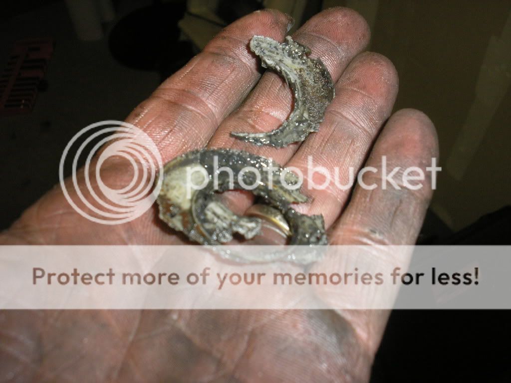

Factory junk.
Designed to break, destined for upgrade.
To see all of my install pics click HERE.
Factory junk.
Designed to break, destined for upgrade.
To see all of my install pics click HERE.
Last edited by Absolute; 08-26-2010 at 09:15 PM.
08-26-2010, 09:03 PM
#7
JK Jedi
Thread Starter
Join Date: Oct 2009
Location: Fresno, California, United States
Posts: 4,760
Likes: 0
Received 0 Likes
on
0 Posts


