Install Write-Up: Rigid Industries Tail Light Kit/SR-Q LED Wiring for JK Wrangler
 06-12-2016, 07:54 AM
#1
JK Newbie
Thread Starter

Join Date: Jan 2011
Location: FWB, FL
Posts: 8
Likes: 0
Received 0 Likes
on
0 Posts
This write-up covers the wiring of the Rigid Industries SR-Q Backup Light Kit into a 2007 JK Wrangler, using the Rugged Ridge A-Pillar Switch Panel as the activation mechanism instead of the supplied switch. I opted to only have these lights on a manual switch, they are NOT spliced into the backup light system. See this link for the write-up on the installation of the backup lights onto the tail lights.
This installation uses the following products:
Rigid Industries 98002 SR-Q Hybrid LED Back Up Light Kit
Rugged Ridge A-Pillar Switch Pod with Switches
Install Time:
About 3 hours, working at a leisurely/comfortable pace.
The following tools are required:
PRE-INSTALLATION NOTES:
This installation is easiest if you start at the ends (battery and tail lights) and work your way to the middle. It is important to note the supplied wiring harness is NOT JK-specific, meaning that you will have WAY more wire than you need. Additionally, the smaller width of the switch connectors and relatively short length of the wiring harness between the switch connectors and the harness relay mean you will need to splice on new connectors as well additional lengths of wire running to the switch so the relay can be adequately hidden. DO NOT USE THIS INSTALLATION GUIDE IF YOU DO NOT FEEL COMFORTABLE DOING WORK ON THE WIRING HARNESS.
I removed the entire interior (seats/plastic trim/center console/carpet) as well as the soft top and doors as I am preparing to install BedTred prior to starting this installation. This helped greatly since I was able to tuck the new wiring harness alongside existing factory wiring harnesses. You do not have to go to nearly that length, but having everything removed was a tremendous help. It will be a tight fit to access the firewall under the driver dash with the driver seat installed, but it can be done.
Also, I already installed the Rugged Ridge switch panel with some other lights I installed, so this write-up will not cover that particular part.
STEP 1:
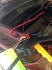
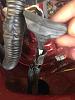
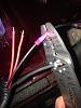
I opted to start at the battery end first. This wiring harness comes with a quick disconnect on the positive end so you don’t have to worry about jamming the inline fuse found on the positive side through the firewall. I have not seen that feature on other Rigid harnesses I have installed, so that was a nice touch. To start, place the entire wiring harness inside the Jeep on the driver seat/floorboard. Disconnect the red (positive) wire with the O-Ring connector at the disconnect, then pop open and prop up the hood. Using a bar clamp or clothespin, secure the O-Ring connector as shown. This will ensure you have enough wire to reach the positive battery terminal. Tuck the positive wire along the factory wiring harnesses running against the firewall.
STEP 2:
Using masking tape, tape the quick disconnect to the metal coat hanger. I tried duct tape first, but found it left a sticky residue behind whereas masking tape did not.

On automatic transmission JKs, there is a foam plug to the right of the brake booster. Mine is difficult to see since I already have a couple of wiring harnesses running through it. This is the most direct and easiest point I have found to run wires through the firewall. This hole is only here on automatics, manual transmission JKs have this hole filled by a clutch booster.
Using the coat hanger, poke through the plug. When you look under the driver dash, you should see the hanger and attached wire poking through. Pull the hanger a little bit more until you can work comfortably. BE CAREFUL, DO NOT PULL THE ENTIRE HANGER THROUGH. Unwrap the positive wire from the hanger and reconnect the disconnect.
STEP 3:
Using masking tape, attach the black (negative cable) with the O-Ring connector to the hanger. Pull the hanger from under the hood until you have as much negative wire pulled through as you can.
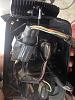
You should notice the relay has pulled up tight against the firewall; this is good because it will keep it out of the way of your feet.
STEP 4:
Tuck the negative cable alongside the positive cable like you did in Step 1 and secure with a bar clamp.
STEP 5:
With the front secured for now, it’s time to run the harness to the back. I started with the driver side. Using the plastic fastener remover, remove the plastic rivets holding the plastic lower kick and seat belt protector panels and remove the panels. Tuck the wiring harness as close to the edge as you can, and reinstall the panels. I don’t have photos of this as I already had them removed for my BedTred preparation.
You should now have a huge pile of harness remaining on the back floor/seat, we’ll deal with this later. Once I got the harness to the B-pillar, I opted to run my harness alongside the factory harness just under the top side of the cargo tub.
STEP 6:
With the harness now at the driver tail light, it’s time to connect the harness to the light! Using a Phillips screwdriver, remove the tail light. Disconnect the factory taillight wiring harness by pressing the tab on the grey connectors and pulling. Gently set the tail light assembly down.
STEP 7:
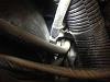
On the top of the body tub is a large rubber grommet; use gentle pressure to pull up and remove it.
STEP 8:
Undo the electrical tape holding the wiring harness to the grommet. You will notice there is a very tight collar/sleeve on the bottom of the grommet. Obviously the connector won’t fit through that, so the sleeve has to go. Gently use the scissors to cut away the sleeve where it tapers into the grommet. BE VERY CAREFUL NOT TO CUT THROUGH THE WIRES INSIDE.
Once the sleeve is cut from the grommet, cut the sleeve bottom-to-top so you can remove it from around the wires.
Alternatively, you could cut the connector from the harness using wire cutters, run the wires through the grommet and then resplice the connector, but I don’t like making more cuts in harnesses than I have to, so I opted to modify the grommet.
STEP 9:
With the grommet prepared, push the connector through the grommet. It will take a little effort, but it can be done.
STEP 10:
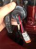
Connect the connector to the SR-Q light, and reconnect the factory grey tail light connector. NOTE: I chose to run the SR-Q light cord between the plug for the factory tail light and a metal clip holding the factory connector. This was done to keep the SR-Q light cord as straight as possible.
STEP 11:
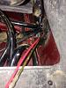
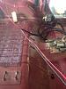
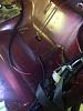
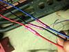
I opted to run the other SR-Q connector along the floor under the carpet to the passenger side B-pillar, then alongside the factory wiring harness at the top of the cargo tub on the passenger side. This caused the wiring harness to raise off the ground as shown below. We’ll deal with that later, but for now repeat steps 6-10 to connect the passenger side SR-Q light.
STEP 12:
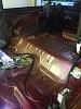
By this time, if your wiring harness is like mine it will be partially up in the air.
This is caused by the plastic wiring loom not being far enough away from where we need the wire paths to go in different directions, so let’s take care of that now. In addition, since the amount of extra wiring harness will be difficult to hide, we can take care of two problems at once.
I decided to cut the wiring harness and remove the surplus lengths of wire, and selected near the lower driver side seat belt mount for my splice point. This was done to keep it out of the way and minimize the chance of it being stepped on.
STEP 13:
Ensure the paths of the wiring harness to the dash, passenger, and driver lights are exactly where you want them. Using scissors, cut away the plastic wiring loom to expose the wires beneath. BE CAREFUL NOT TO CUT THE WIRES INSIDE THE LOOM. Once the wires are exposed, cut each of the four wires using wire cutters.
Find the point where the harness coming from the dash intersects your splice point. Just like you did for the wires running to the tail lights, cut away the loom and clip the wires with wire cutters. Remove the extra loom and wire. If you have exposed wires in your installation not covered by a loom, you can use the loom you just removed to cover them up.
When all is said and done, you should have something that looks like this:
STEP 14:
With the extra wiring harness removed, we should have just enough remaining to get a good, clean install. Of course, we will need to reconnect the harness. The wires running to the lights are all 18 gauge, so we can use 18 gauge insulated butt connectors and a crimping tool to splice the wires back together. As long as you go red-to-red and black-to-black, it doesn’t matter which wires get spliced back together.
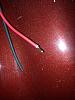
To prepare the wires for splicing, use a wire stripper to strip off approx. 1/4" of insulation off each wire.
STEP 15:
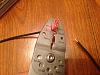
Once all the wires are prepared, you can start crimping! Insert the end of each wire into an 18 gauge butt connector, and use the crimping tool to securely splice the wires. AGAIN, MAKE SURE YOU’RE CRIMPING RED-TO-RED AND BLACK-TO-BLACK.
When it’s all done it should look like this:
STEP 16:
Tuck the harness you just spliced under the carpet to ensure a clean install. With the lights wired, it’s time to turn attention to the switch.
STEP 17:
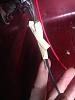
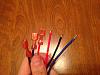
The first thing you’ll notice when you try to connect the paddle connectors on the ends of the red, black, and blue wires to the Rugged Ridge switch is they aren’t the right size!
If you’re using the Rigid-supplied switch they’ll work fine, but for our install, we’re using the Rugged Ridge A-Pillar kit, which uses 1/4" connectors instead of 3/16.” So, bust out those handy wire cutters again and remove those too-small ends!
Also, by this time you’ll have noticed there’s not nearly enough wire to connect the switch to the rest of the harness, so once again, we’ll have to solve two problems at once.
STEP 18:
The wires connecting the relay to the switch are 20 gauge, and you’ll need at least 3 feet more of each wire to make it work. Luckily, we have a ton of extra red and black wire laying around since we just cut it out. Even though the red/black are 18 gauge and wires going to the switch are 20 gauge, you can splice them together.
Of course, you could also use more of the extra black or red wire to make the jumper for the blue wire as well (or just not connect it, the blue wire just lights up the switch when it is “on”), but I like to keep my wire colors matching to avoid confusion (nothing more frustrating/scary than following a green wire expecting an auxiliary feed and discovering it is spliced to a positive red wire, making it live), so I went to my local boat store and picked up a 3’ length of 18 gauge blue wire.
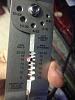
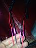
Strip off 1/4" of insulation from each end of your 3’ wires. Using a wire crimper, crimp on a 18 gauge 1/4" female paddle connector to one end on each of the wires.
When done, it should look like this:
STEP 19:
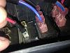
Use insulated butt connectors to connect your extension wires back into the wiring harness, keeping in mind red-to-red, black-to-black, and blue-to-blue. The butt connectors should accept a series of gauges (mine were 18-22) so you can splice different wire sizes together. When done it should look like this:
STEP 20:
Now it’s time to connect the paddles to the switch so the circuit can be tested. The way I have my switches set, blue is to the right, red is to the middle, and black is to the left. Ensure the paddle connectors seat securely to the switch posts. Ensure the switch is in the “off” position since the circuit is about to be energized.
STEP 21:
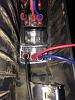
With everything in place, it’s time for a test! Remove the lens covers from the lights (if you have them on), unclamp the O-Ring connectors and secure them to the battery (black to black (-) and red to red (+)). Flip the switch to the “on” position. If everything works as it should, you should see something like this!
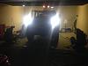
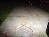
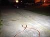
For reference, that is a 30-foot tape measure with 0” at the lights. The lights are at their full downward deflection, giving you an idea of their brightness and throw.
STEP 22:
With everything working, it’s time to tidy up the installation. I like to do this part with the lights on, so if something you do causes the lights to go out (loose connection, pinched wire, etc) you can immediately stop, troubleshoot, and correct the issue. BE VERY CAREFUL WHILE DOING THIS SINCE THE SYSTEM IS ENERGIZED. Some cleanup steps include:
This concludes my install write-up for wiring the SR-Q lights, hope it helped!
This installation uses the following products:
Rigid Industries 98002 SR-Q Hybrid LED Back Up Light Kit
Rugged Ridge A-Pillar Switch Pod with Switches
Install Time:
About 3 hours, working at a leisurely/comfortable pace.
The following tools are required:
- Bar clamp or clothespin
- Straightened metal hanger
- Masking Tape
- Phillips Screwdriver
- Scissors
- Wire Cutter/Stripper/Crimper
- Plastic Fastener Remover
- 3 18-22 gauge 1/4" female disconnects
- 7 18-22 gauge insulated butt connectors
- 3’ blue 20 gauge or larger (18 or 16) wire
- Zipties
- Electrical Tape
PRE-INSTALLATION NOTES:
This installation is easiest if you start at the ends (battery and tail lights) and work your way to the middle. It is important to note the supplied wiring harness is NOT JK-specific, meaning that you will have WAY more wire than you need. Additionally, the smaller width of the switch connectors and relatively short length of the wiring harness between the switch connectors and the harness relay mean you will need to splice on new connectors as well additional lengths of wire running to the switch so the relay can be adequately hidden. DO NOT USE THIS INSTALLATION GUIDE IF YOU DO NOT FEEL COMFORTABLE DOING WORK ON THE WIRING HARNESS.
I removed the entire interior (seats/plastic trim/center console/carpet) as well as the soft top and doors as I am preparing to install BedTred prior to starting this installation. This helped greatly since I was able to tuck the new wiring harness alongside existing factory wiring harnesses. You do not have to go to nearly that length, but having everything removed was a tremendous help. It will be a tight fit to access the firewall under the driver dash with the driver seat installed, but it can be done.
Also, I already installed the Rugged Ridge switch panel with some other lights I installed, so this write-up will not cover that particular part.
STEP 1:
I opted to start at the battery end first. This wiring harness comes with a quick disconnect on the positive end so you don’t have to worry about jamming the inline fuse found on the positive side through the firewall. I have not seen that feature on other Rigid harnesses I have installed, so that was a nice touch. To start, place the entire wiring harness inside the Jeep on the driver seat/floorboard. Disconnect the red (positive) wire with the O-Ring connector at the disconnect, then pop open and prop up the hood. Using a bar clamp or clothespin, secure the O-Ring connector as shown. This will ensure you have enough wire to reach the positive battery terminal. Tuck the positive wire along the factory wiring harnesses running against the firewall.
STEP 2:
Using masking tape, tape the quick disconnect to the metal coat hanger. I tried duct tape first, but found it left a sticky residue behind whereas masking tape did not.
On automatic transmission JKs, there is a foam plug to the right of the brake booster. Mine is difficult to see since I already have a couple of wiring harnesses running through it. This is the most direct and easiest point I have found to run wires through the firewall. This hole is only here on automatics, manual transmission JKs have this hole filled by a clutch booster.
Using the coat hanger, poke through the plug. When you look under the driver dash, you should see the hanger and attached wire poking through. Pull the hanger a little bit more until you can work comfortably. BE CAREFUL, DO NOT PULL THE ENTIRE HANGER THROUGH. Unwrap the positive wire from the hanger and reconnect the disconnect.
STEP 3:
Using masking tape, attach the black (negative cable) with the O-Ring connector to the hanger. Pull the hanger from under the hood until you have as much negative wire pulled through as you can.
You should notice the relay has pulled up tight against the firewall; this is good because it will keep it out of the way of your feet.
STEP 4:
Tuck the negative cable alongside the positive cable like you did in Step 1 and secure with a bar clamp.
STEP 5:
With the front secured for now, it’s time to run the harness to the back. I started with the driver side. Using the plastic fastener remover, remove the plastic rivets holding the plastic lower kick and seat belt protector panels and remove the panels. Tuck the wiring harness as close to the edge as you can, and reinstall the panels. I don’t have photos of this as I already had them removed for my BedTred preparation.
You should now have a huge pile of harness remaining on the back floor/seat, we’ll deal with this later. Once I got the harness to the B-pillar, I opted to run my harness alongside the factory harness just under the top side of the cargo tub.
STEP 6:
With the harness now at the driver tail light, it’s time to connect the harness to the light! Using a Phillips screwdriver, remove the tail light. Disconnect the factory taillight wiring harness by pressing the tab on the grey connectors and pulling. Gently set the tail light assembly down.
STEP 7:
On the top of the body tub is a large rubber grommet; use gentle pressure to pull up and remove it.
STEP 8:
Undo the electrical tape holding the wiring harness to the grommet. You will notice there is a very tight collar/sleeve on the bottom of the grommet. Obviously the connector won’t fit through that, so the sleeve has to go. Gently use the scissors to cut away the sleeve where it tapers into the grommet. BE VERY CAREFUL NOT TO CUT THROUGH THE WIRES INSIDE.
Once the sleeve is cut from the grommet, cut the sleeve bottom-to-top so you can remove it from around the wires.
Alternatively, you could cut the connector from the harness using wire cutters, run the wires through the grommet and then resplice the connector, but I don’t like making more cuts in harnesses than I have to, so I opted to modify the grommet.
STEP 9:
With the grommet prepared, push the connector through the grommet. It will take a little effort, but it can be done.
STEP 10:
Connect the connector to the SR-Q light, and reconnect the factory grey tail light connector. NOTE: I chose to run the SR-Q light cord between the plug for the factory tail light and a metal clip holding the factory connector. This was done to keep the SR-Q light cord as straight as possible.
STEP 11:
I opted to run the other SR-Q connector along the floor under the carpet to the passenger side B-pillar, then alongside the factory wiring harness at the top of the cargo tub on the passenger side. This caused the wiring harness to raise off the ground as shown below. We’ll deal with that later, but for now repeat steps 6-10 to connect the passenger side SR-Q light.
STEP 12:
By this time, if your wiring harness is like mine it will be partially up in the air.
This is caused by the plastic wiring loom not being far enough away from where we need the wire paths to go in different directions, so let’s take care of that now. In addition, since the amount of extra wiring harness will be difficult to hide, we can take care of two problems at once.
I decided to cut the wiring harness and remove the surplus lengths of wire, and selected near the lower driver side seat belt mount for my splice point. This was done to keep it out of the way and minimize the chance of it being stepped on.
STEP 13:
Ensure the paths of the wiring harness to the dash, passenger, and driver lights are exactly where you want them. Using scissors, cut away the plastic wiring loom to expose the wires beneath. BE CAREFUL NOT TO CUT THE WIRES INSIDE THE LOOM. Once the wires are exposed, cut each of the four wires using wire cutters.
Find the point where the harness coming from the dash intersects your splice point. Just like you did for the wires running to the tail lights, cut away the loom and clip the wires with wire cutters. Remove the extra loom and wire. If you have exposed wires in your installation not covered by a loom, you can use the loom you just removed to cover them up.
When all is said and done, you should have something that looks like this:
STEP 14:
With the extra wiring harness removed, we should have just enough remaining to get a good, clean install. Of course, we will need to reconnect the harness. The wires running to the lights are all 18 gauge, so we can use 18 gauge insulated butt connectors and a crimping tool to splice the wires back together. As long as you go red-to-red and black-to-black, it doesn’t matter which wires get spliced back together.
To prepare the wires for splicing, use a wire stripper to strip off approx. 1/4" of insulation off each wire.
STEP 15:
Once all the wires are prepared, you can start crimping! Insert the end of each wire into an 18 gauge butt connector, and use the crimping tool to securely splice the wires. AGAIN, MAKE SURE YOU’RE CRIMPING RED-TO-RED AND BLACK-TO-BLACK.
When it’s all done it should look like this:
STEP 16:
Tuck the harness you just spliced under the carpet to ensure a clean install. With the lights wired, it’s time to turn attention to the switch.
STEP 17:
The first thing you’ll notice when you try to connect the paddle connectors on the ends of the red, black, and blue wires to the Rugged Ridge switch is they aren’t the right size!
If you’re using the Rigid-supplied switch they’ll work fine, but for our install, we’re using the Rugged Ridge A-Pillar kit, which uses 1/4" connectors instead of 3/16.” So, bust out those handy wire cutters again and remove those too-small ends!
Also, by this time you’ll have noticed there’s not nearly enough wire to connect the switch to the rest of the harness, so once again, we’ll have to solve two problems at once.
STEP 18:
The wires connecting the relay to the switch are 20 gauge, and you’ll need at least 3 feet more of each wire to make it work. Luckily, we have a ton of extra red and black wire laying around since we just cut it out. Even though the red/black are 18 gauge and wires going to the switch are 20 gauge, you can splice them together.
Of course, you could also use more of the extra black or red wire to make the jumper for the blue wire as well (or just not connect it, the blue wire just lights up the switch when it is “on”), but I like to keep my wire colors matching to avoid confusion (nothing more frustrating/scary than following a green wire expecting an auxiliary feed and discovering it is spliced to a positive red wire, making it live), so I went to my local boat store and picked up a 3’ length of 18 gauge blue wire.
Strip off 1/4" of insulation from each end of your 3’ wires. Using a wire crimper, crimp on a 18 gauge 1/4" female paddle connector to one end on each of the wires.
When done, it should look like this:
STEP 19:
Use insulated butt connectors to connect your extension wires back into the wiring harness, keeping in mind red-to-red, black-to-black, and blue-to-blue. The butt connectors should accept a series of gauges (mine were 18-22) so you can splice different wire sizes together. When done it should look like this:
STEP 20:
Now it’s time to connect the paddles to the switch so the circuit can be tested. The way I have my switches set, blue is to the right, red is to the middle, and black is to the left. Ensure the paddle connectors seat securely to the switch posts. Ensure the switch is in the “off” position since the circuit is about to be energized.
STEP 21:
With everything in place, it’s time for a test! Remove the lens covers from the lights (if you have them on), unclamp the O-Ring connectors and secure them to the battery (black to black (-) and red to red (+)). Flip the switch to the “on” position. If everything works as it should, you should see something like this!
For reference, that is a 30-foot tape measure with 0” at the lights. The lights are at their full downward deflection, giving you an idea of their brightness and throw.
STEP 22:
With everything working, it’s time to tidy up the installation. I like to do this part with the lights on, so if something you do causes the lights to go out (loose connection, pinched wire, etc) you can immediately stop, troubleshoot, and correct the issue. BE VERY CAREFUL WHILE DOING THIS SINCE THE SYSTEM IS ENERGIZED. Some cleanup steps include:
- Ziptie wiring harnesses to firewall/cargo tub
- Ziptie relay in driver foot well
- Electrical tape/heat shrink all butt connectors.
- Electrical tape grommets in back to wiring harness
- Tuck wiring harness under carpet
This concludes my install write-up for wiring the SR-Q lights, hope it helped!

