OEM TIPM Study
 04-23-2011, 01:38 PM
#1
JK Jedi Master
Thread Starter
The Totally Integrated Power Module (TIPM) is a lot more than the fuse box it appears to be. It is responsible for a lot of the power switching/modulation/distribution, and communications with other systems in the JK electrical system.
New TIPMs go for $200 - $250. Used can be found for $0 - $200; very negotiable. After replacing the TIPM, it may need to be programmed to the vehicle. As far as I know, only the dealer can do the programming.
This is from the factory service manual:
The original Cab Compartment Node and Powertrain Control Module must be installed and functioning properly prior to powering up the new TIPM. The TIPM receives vehicle configuration data from the CCN and Vehicle Identification Number information from the PCM. If configuration information becomes lost or corrupted, the data can be obtained from DealerCONNECT
I found a TIPM from a wreck, (the TIPM took a hit, too), so I salvaged the useable parts, and didn't mind disassembling it to see how it is made.
I couldn't find a detailed wiring diagram for the TIPM, so this is more a visual than technical presentation.
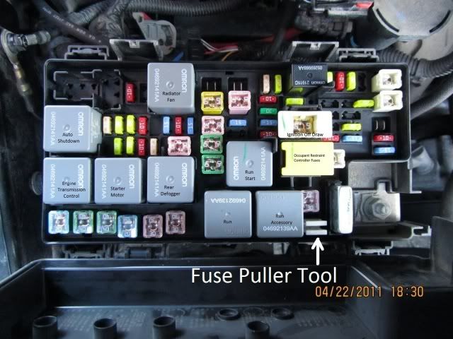
This is a view of the TIPM as it sits in the engine bay.

Looking down on the TIPM with the cover open. There is a diagram and legend on the inside of the cover. The square gray items are mechanical relays. The item labeled "Ignition Off Draw" is the one you pull up to minimize the drain on the battery if the vehicle will not be run for an extended time. (Up to 30 days. Longer than that, disconnect the battery, and charge it periodically.)
The item labeled "Occupant Restraint Controller" should not be relied upon to make safe the ballistic components of the system. All instructions say to disconnect the battery negative terminal and wait several minutes to make it safe.
Here is a view of a relay with the cover removed.

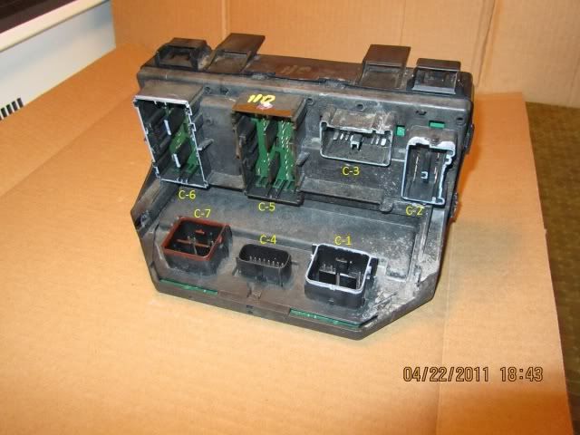
A view underneath the TIPM.
The bottom cover has been removed, exposing the TIPM circuit board. Also, the layers of connector prongs have been separated. The view is looking up from the bottom.
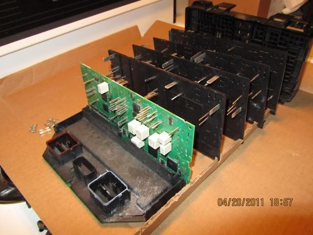
This view is from the top looking down. The fuses and relays have been removed, since with the separated layers, there are no connector prongs in the sockets to retain them. Notice how the prongs on each layer are connected, and that all the prongs stick through each of the layers above and below (previous photo, too).
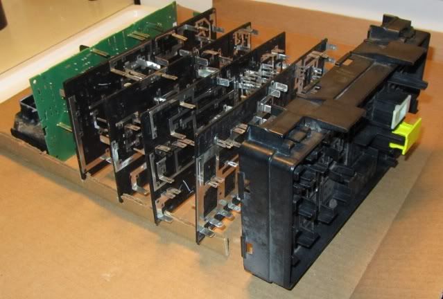
All the layers, back together.

A good view of the "brain" of the TIPM. In addition to the IC's and such, there are mechanical relays in the 7 white components on the board. It is this portion of the TIPM that is not serviceable by the dealer or consumer.
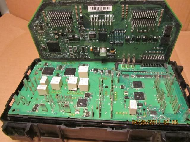
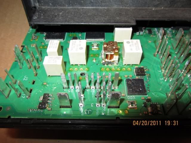
Here are two views of the relays on the circuit board. The bigger ones are double relays, the smaller are single.

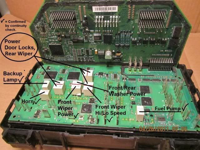
Here is my best effort to identify the relays on the circuit board.
The check mark by the name indicates I was able to verify what it controls by tracing the circuit, exclusively between relay and destination, with a continuity tester. On the rest of them there were too many common points among them to isolate each relay.
When each of the systems was energized, I could hear the click of a relay with the aid of a mechanic's stethoscope, (not one of the big relays in the fuse box section of the TIPM).
There was no click sound when the headlights and fog lights were turned on, indicating those are controlled with a solid state relay.
New TIPMs go for $200 - $250. Used can be found for $0 - $200; very negotiable. After replacing the TIPM, it may need to be programmed to the vehicle. As far as I know, only the dealer can do the programming.
This is from the factory service manual:
The original Cab Compartment Node and Powertrain Control Module must be installed and functioning properly prior to powering up the new TIPM. The TIPM receives vehicle configuration data from the CCN and Vehicle Identification Number information from the PCM. If configuration information becomes lost or corrupted, the data can be obtained from DealerCONNECT
I found a TIPM from a wreck, (the TIPM took a hit, too), so I salvaged the useable parts, and didn't mind disassembling it to see how it is made.
I couldn't find a detailed wiring diagram for the TIPM, so this is more a visual than technical presentation.
This is a view of the TIPM as it sits in the engine bay.
Looking down on the TIPM with the cover open. There is a diagram and legend on the inside of the cover. The square gray items are mechanical relays. The item labeled "Ignition Off Draw" is the one you pull up to minimize the drain on the battery if the vehicle will not be run for an extended time. (Up to 30 days. Longer than that, disconnect the battery, and charge it periodically.)
The item labeled "Occupant Restraint Controller" should not be relied upon to make safe the ballistic components of the system. All instructions say to disconnect the battery negative terminal and wait several minutes to make it safe.
Here is a view of a relay with the cover removed.
A view underneath the TIPM.
The bottom cover has been removed, exposing the TIPM circuit board. Also, the layers of connector prongs have been separated. The view is looking up from the bottom.
This view is from the top looking down. The fuses and relays have been removed, since with the separated layers, there are no connector prongs in the sockets to retain them. Notice how the prongs on each layer are connected, and that all the prongs stick through each of the layers above and below (previous photo, too).
All the layers, back together.
A good view of the "brain" of the TIPM. In addition to the IC's and such, there are mechanical relays in the 7 white components on the board. It is this portion of the TIPM that is not serviceable by the dealer or consumer.
Here are two views of the relays on the circuit board. The bigger ones are double relays, the smaller are single.
Here is my best effort to identify the relays on the circuit board.
The check mark by the name indicates I was able to verify what it controls by tracing the circuit, exclusively between relay and destination, with a continuity tester. On the rest of them there were too many common points among them to isolate each relay.
When each of the systems was energized, I could hear the click of a relay with the aid of a mechanic's stethoscope, (not one of the big relays in the fuse box section of the TIPM).
There was no click sound when the headlights and fog lights were turned on, indicating those are controlled with a solid state relay.
Last edited by ronjenx; 02-29-2012 at 06:27 PM.

The following users liked this post:
R3v3n4n7 (05-03-2024)
04-23-2011, 03:14 PM
#2
JK Enthusiast

Join Date: Feb 2011
Location: Gulfport
Posts: 132
Likes: 0
Received 0 Likes
on
0 Posts
Apparently mine went out. My blower motor will turn on by itself if I dont turn it all the way off when I leave the vehicle. I have to bring it in monday for the stealership so they can replace it, It is costing me $100 for the warranty deductable.
04-23-2011, 03:24 PM
#3
JK Jedi Master
Thread Starter
The data sheet for those relays says they are good for 100,000 cycles.
 04-24-2011, 12:45 AM
#7
JK Newbie
Join Date: Jan 2011
Location: LA, CA
Posts: 49
Likes: 0
Received 0 Likes
on
0 Posts
Very interesting, the tin plated connectors scare me a bit though. In the relay it looks like a 680 ohm resistor for coil supression. Their drivers may allow for that pulse, though diodes are more common as you don't get as big a pulse. Maybe the drivers are those chips at the back as I can't see the multipin flatpacs having the power capability. Omron is a big company and the numbers are probably Mopar, but I'm sure you could find substitutes at the big electronics sellers. I do like that they are still using mechanical relays. Thanks for the pictures and info.
Trending Topics
04-24-2011, 07:20 AM
#8
JK Jedi Master
Thread Starter
Very interesting, the tin plated connectors scare me a bit though. In the relay it looks like a 680 ohm resistor for coil supression. Their drivers may allow for that pulse, though diodes are more common as you don't get as big a pulse. Maybe the drivers are those chips at the back as I can't see the multipin flatpacs having the power capability. Omron is a big company and the numbers are probably Mopar, but I'm sure you could find substitutes at the big electronics sellers. I do like that they are still using mechanical relays. Thanks for the pictures and info.
04-24-2011, 08:12 AM
#9
JK Super Freak
Very interesting, the tin plated connectors scare me a bit though. In the relay it looks like a 680 ohm resistor for coil supression. Their drivers may allow for that pulse, though diodes are more common as you don't get as big a pulse. Maybe the drivers are those chips at the back as I can't see the multipin flatpacs having the power capability. Omron is a big company and the numbers are probably Mopar, but I'm sure you could find substitutes at the big electronics sellers. I do like that they are still using mechanical relays. Thanks for the pictures and info.
 04-24-2011, 08:30 AM
#10
JK Jedi Master
Thread Starter
I wouldn't remove/disassemble the TIPM for cleaning purposes. If the TIPM is operating properly, there is no need to jeopardize it. It appears to me that the contacts on the removable items are designed to scratch into the contact surfaces upon installation, creating a good metal to metal contact. The light corrosion (if it is corrosion) on the unused contact surfaces doesn't seem to be detrimental.
Removing and installing the same or new TIPM will not require dealer programming if the CCN and PCM are installed and operating properly.
I don't know if this applies to a used TIPM from another vehicle.
TIPM Installation:
1. Position the TIPM into the engine compartment.
2. Connect each of the seven TIPM wire harness connectors.
3. Position the TIPM onto the mounting bracket and push down until the mounting clips are fully seated.
4. Position the TIPM positive cable onto the mounting stud and install the retaining nut. Tighten the nut to 80 - 100 in. lbs.
5. Open the TIPM cover and fully seat the Airbag fuse holder (two fuses in one yellow carrier) and the Ignition Off Draw (IOD) fuse.
6. Connect the battery negative cable.
7. Close the hood.
8. Insert the ignition key and turn it to the “RUN” position and wait twelve seconds. The TIPM will collect the necessary vehicle configuration and VIN data from the CCN and PCM at this time. After twelve seconds turn the ignition key to the “OFF” position and then back to the “ON” position and verify proper vehicle systems operation.
If the information was lost or corrupted, it can be retrieved with the StarScan tool through DealerConnect.
Last edited by ronjenx; 04-24-2011 at 10:02 AM.