Completed Writeup - Stereo Upgrade JKU Infinity Retaining OEM H/U
 04-09-2012, 11:27 AM
#1
JK Newbie
Thread Starter

This has been a process long in the making, and I'm glad it's almost done. I will say, however, I am far more intimate with my Jeep now than I was before. Not like the 'Making out with my car" thing on TLC, but I have gained an enormous amount of understanding of the systems and components.
Component List:
2011 Jeep Sahara Unlimited with Infinity OEM sound system.
2 x Alpine SPS-610C 6.5" Component with remote tweeter for front.
2 x Alpine SPS-610 6.5" 2 way Rears
10" Kicker sub
Kicker ZX10Sum8 Summing LOC
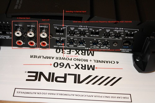
Alpine MRX-V60 4 channel amp + mono Sub out.
Jeep Wiring and component diagrams, with exploded views and individual part numbers / price.
http://www.jeep4x4center.com/jeep-parts/index.htm
Mopar connector repair/replacement, including pinout listings for ALL OEM CONNECTORS!!!
http://dto.vftis.com/mopar/platform_...asp?return=new
When I refer to the term "Channel", it consists of single speaker signal, entailing both the + and - terminals. (Your "Front Right" speaker uses one "Channel")
As mentioned, I am upgrading the entire sound system, aside from OEM H/U, to retain the bluetooth, nav, mygig, etc.
This is by no means a complicated upgrade, but being a Paramedic, I have a need to preplan, and know exactly what I am getting into prior to proceeding. All I can suggest to anyone doing this, is to read, read, read, understand the wiring and interface, and how everything works together BEFORE you attempt. Of course, by using any of this info / suggestions, you do so at your own risk.
OK here we go. It's gonna be lengthy, but it's what I was looking for - an explanation mixed with a how-to.
To start, I searched the ends of the internet for wiring diagrams, pinout connections, etc. Below is what I have confirmed to be accurate.
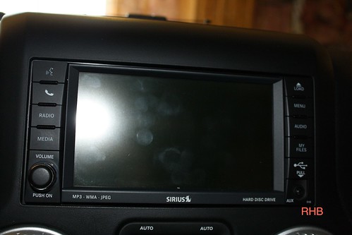
RHB MyGig by imedic31, on Flickr
The Infinity system consists of the head unit & relates attachments (Bluetooth, HD, Nav, Sat Radio), System amplifier, speakers and Sub. Your signal from your head unit is relayed to the Infinity amp, where it is processed. Each set of speakers are fed a custom tuned audio signal. (Ever notice your front woofers have more sound and bass than your overhead Pod speakers in the rear? Thats due to the signal processing.) Your volume, fade/balance, etc is modified by the Infinity amp, not the H/U, which is the norm for aftermarket systems. The head unit communicates via CanBus system, and it's those signals that control the volume/output fade/balance of the system. Due to this fact, we need to tap into the system *after* the OEM amplifier. There are 8 channels of sound to work with, and unless you use a signal summing device to capture and reform a normal audio signal, all you will be doing is amplifying the OEM signal - which has been processed and stripped of vital sound info, and still sound like crap. Just like a an electronic copy of a song, the higher bit rate, the better the sound quality. By not "summing" the channels prior to amplifying, you get the equivalent of a crappy mp3 recording that sounds tinny, digitized, and basically louder, but still crap.
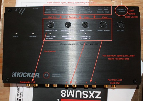
In order to fix the sound, using some type of signal processor / audio sum device is needed. As there are 8 channels (meaning L+R tweeters, L+R fronts, L+R rears, and 2 sub outputs) of OEM audio, you "should" use a device capable of handling 8 speaker level signals. As you can see in the picture, the kicker Xsum accepts 8 channels of audio, sums them (recreates a full audio spectrum from the OEM amp), allows you to tweek them a touch, and outputs a low level RCA output, which can feed an aftermarket amp.
IMG_1277 by imedic31, on Flickr
IMG_1278 by imedic31, on Flickr
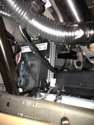
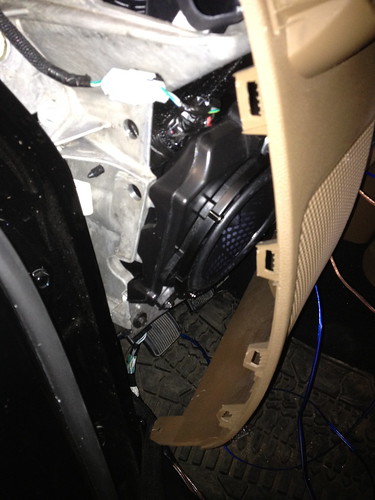
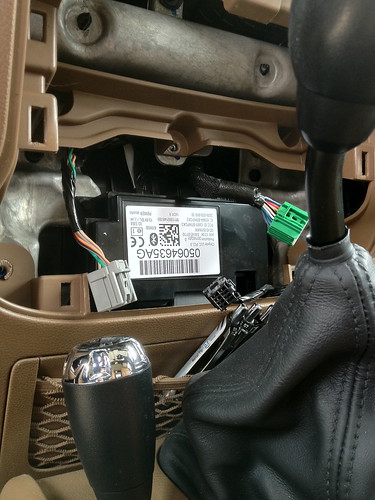
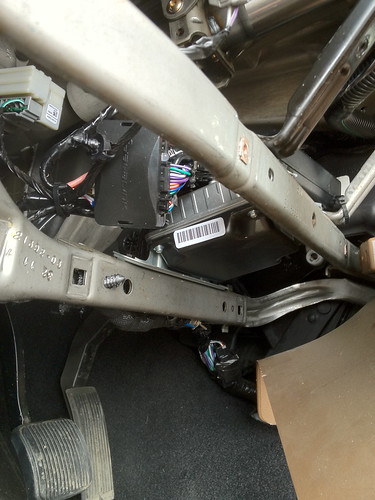
The location of the Infinity amp is behind the drivers kick panel. There is no need to remove the amp to gain access to the wiring, but I wanted a good look, so I took it out.
IMG_1501 by imedic31, on Flickr
IMG_1482 by imedic31, on Flickr
IMG_1486 by imedic31, on Flickr
There are numerous locations to access the OEM wiring, but I liked the idea of being close to the source, and an easy 12v power tap.
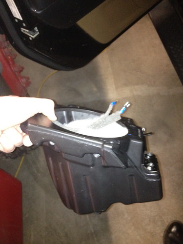
There are two connectors on the bottom of the Infinity amp. One is an input connector (White 22Pin), getting audio from H/U, power, Canbus signal, etc.
The other connector (Black 16 Pin) contains all of the output audio signals, EXCEPT front tweeter signals. These tweeter signals come from the "input" connector, presumably just a simple passthrough, as there isn't much power required to drive a tweeter.
IMG_1484 by imedic31, on Flickr
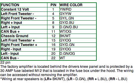
22 pin amplifier supplyLARGE by imedic31, on Flickr
The above 22 pin connector is the Amps 'Input'. Both the 22Pin and 16Pin connectors plug into the 'bottom' of the amp, when the amp is installed in it's location.
22PinListSpeaker by imedic31, on Flickr
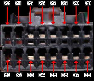
16 pin amplifier out by imedic31, on Flickr

16PinListing by imedic31, on Flickr
Pinout listing for both - colors and pin #'s confirmed to be 100% accurate for a 2011 Sahara Unlimited.
Just for Info Purposes:
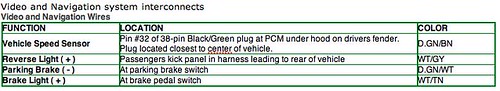
VidNavInterconnect by imedic31, on Flickr
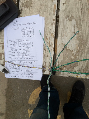
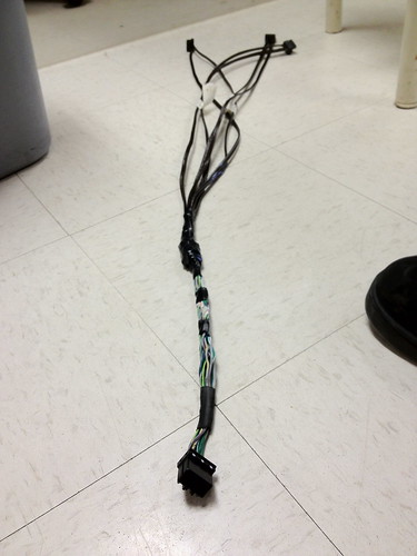
To make things easier for me, I pre-spliced my connections (speaker level inputs) into the Kicker Sum/LOC. When I was comfortable enough that I had the correct wiring harness, and that everything matched up, I clipped the OEM amps output wiring, ensuring I had plenty of wire left. I wired this 16Pin connector to my pre-made connections feeding the kicker, and that was all it took. Plug the harness back into the OEM Amp, and my speaker level inputs are complete. Almost. lol..

IMG_1488 by imedic31, on Flickr
IMG_1490 by imedic31, on Flickr
Now attaching my pre-made connections to my kicker Sum/Loc... nicely taped and bundled for easier handling..
IMG_1494 by imedic31, on Flickr
Going back to the 22Pin connector (White one above) you'll notice the two OEM tweeter feeds 'leaving' the OEM Amp 'Input' connector to feed the tweeters. Splicing into the wiring allows me to connect that signal / channel as well, ensuring that I am not missing any OEM signal.
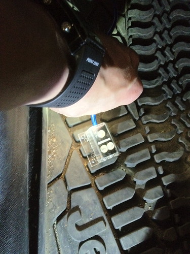
Now that we have our audio source done, we need to provide power to the Kicker Sum/LOC AND the aftermarket amp. There is a temptation to tap the cigarette lighter or the 12v accessory plug. I'd suggest you didn't. They used to be very appropriate 12v constant sources in older vehicles, but with TIPM's and whatnot nowadays, I'd just leave them. Your best option is to provide a stand alone 12v source, directly from the battery. This is the safest and most reliable method, and you can (should) use an inline fuse to prevent damage to your aftermarket equipment (and your vehicle for that matter.)
I ran my 12v power cable through an existing grommet in the firewall. The only thing that goes through there is the rear wiper washer fluid supply hose. I left the wire shielding off for the moment to help see it (Blue). Anytime you run wiring through an engine compartment, it should be protected from the heat and other road elements by using some type of wrap or shielding.
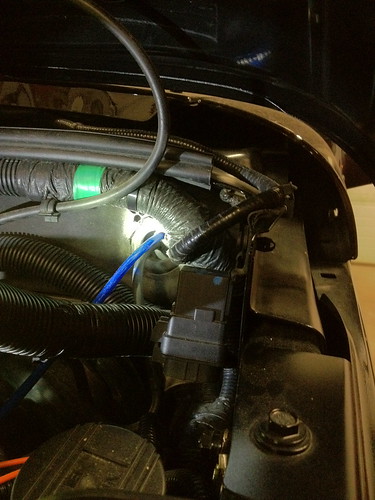
IMG_1495 by imedic31, on Flickr
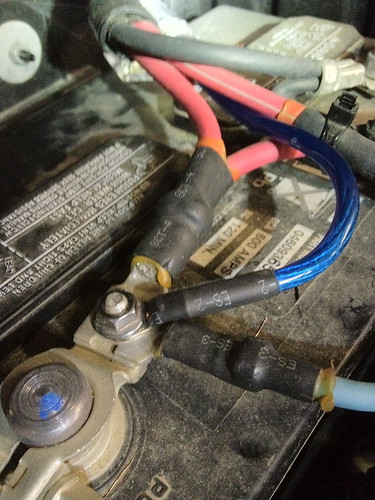
From there, I added an inline fuse, and connected to the positive terminal of my battery. Try to position the fuse as close as possible to the battery... if something causes a short, the fuse blows, and eliminates power to the entire line. Your short / fault would need to occur nearly right at the battery in order to cause fire / damage. It also allows easy access to the fuse should it ever happen to blow.
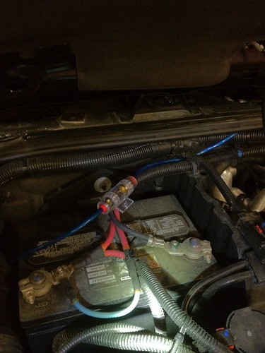
IMG_1497 by imedic31, on Flickr
IMG_1499 by imedic31, on Flickr
Another fuse note... leave it out until you are finished connecting everything. No reason to make your line 'live' while farting around with the wiring.
So... Now we have our audio source, our power, and grounds (There are a bazillion grounding locations in the Jeep...Find the closest one for your preference) Now we need to upgrade those POS OEM speakers.
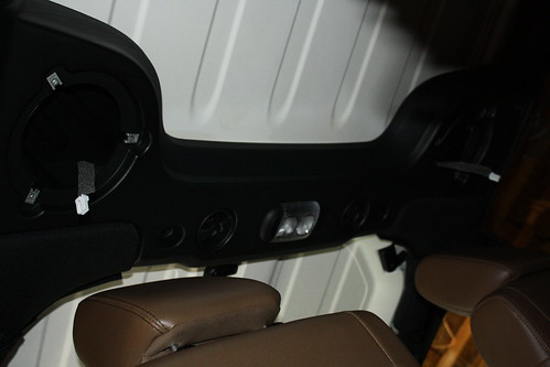
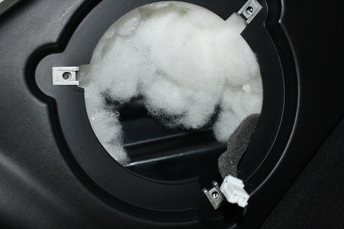
The rear overhead pods are a no brainer, so I won't say much about them. BUT... here is a pick after OEM speakers removed, and voids filled with polyfill.
5$ at walmart... will reduce the tinny or hollow sounding speaker bar.

Polyfill by imedic31, on Flickr
IMG_1282 by imedic31, on Flickr
IMG_1287 by imedic31, on Flickr
As you have probably read on here before, the front speaker pods are a PITA!!!
Anyway, I found it easier to take them right out, make connections, stuff with polyfill, replace OEM POS speakers, and replace into the positions found. On a side note, there are two screws securing the sides, with 7mm heads. There is also on on the bottom attaching the pod to the dash frame. This is a 10mm head, or you can use a hex key... cannot recall the size atm...
IMG_1503 by imedic31, on Flickr
Definitely easier to manage with pod removed.
IMG_1502 by imedic31, on Flickr
Now for the tweeters... You may wish to leave them OEM, but WHY? lol. These are a little more adventurous to install, as it involves trimming / enlarging the hole (for my tweeters anyways..). Just be sure to take your time, measure, fit, cut, fit, cut, measure, fit, etc. Working slowly and by repeatedly checking the fitment, will save you an ugly eyesore (if thats something your into..lol) I used a dremmel, which worked well for me.

IMG_1290 by imedic31, on Flickr
And here is one finished. That dash material gets friggin everywhere... just so you know..
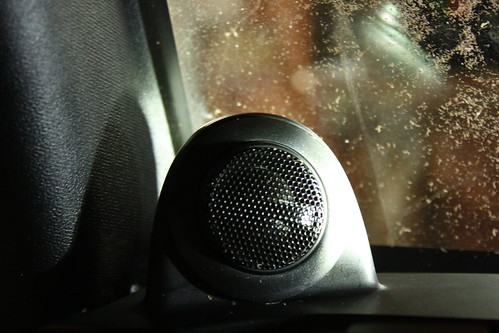
IMG_1291 by imedic31, on Flickr
The passenger side front speaker and tweeter are duplicates of the driver side... although there is less free play in the dash to move things around. I found that unbolting the side screws, then the bottom one for the speaker pod, and turning the pod 90 Deg counter clockwise made it super easy to remove the pod through the glove compartment opening. (Glove comp. removed of course...)
Sooooo... That about wraps it up. The rest is pretty easy to move through, like running your wires, finding grounds, etc, so they are not touched on in this write up. I replaced all of the OEM speaker wire with new stuff. I also put in a splitter off of my main 12v battery source. One to the Kicker, and one to the Alpine amp.
IMG_1500 by imedic31, on Flickr
Also, here are a few more pics of items and their locations...
Bluetooth module:
IMG_1480 by imedic31, on Flickr
And I think this is a Hard Drive, but not 100% sure... (The item with the white barcode on it... the other module in the picture is an iDataLink for my viper alarm/starter..)
IMG_1483 by imedic31, on Flickr
Well, hopefully this is of some use to someone. I've never seen a full write up about this, which is odd.... cause there are hundreds & hundreds of posts asking about this stuff. As for the OEM POS sub, I'll be removing it, and am planning on making the old sub location into a secure storage spot, or just somewhere to keep extra gear / fluids / maybe a tool box. Anyway... happy trailing
Oh - and this system rocks! lol. Crystal clear with top down/off at highway speeds. Giggity!!!
Component List:
2011 Jeep Sahara Unlimited with Infinity OEM sound system.
2 x Alpine SPS-610C 6.5" Component with remote tweeter for front.
2 x Alpine SPS-610 6.5" 2 way Rears
10" Kicker sub
Kicker ZX10Sum8 Summing LOC
Alpine MRX-V60 4 channel amp + mono Sub out.
Jeep Wiring and component diagrams, with exploded views and individual part numbers / price.
http://www.jeep4x4center.com/jeep-parts/index.htm
Mopar connector repair/replacement, including pinout listings for ALL OEM CONNECTORS!!!
http://dto.vftis.com/mopar/platform_...asp?return=new
When I refer to the term "Channel", it consists of single speaker signal, entailing both the + and - terminals. (Your "Front Right" speaker uses one "Channel")
As mentioned, I am upgrading the entire sound system, aside from OEM H/U, to retain the bluetooth, nav, mygig, etc.
This is by no means a complicated upgrade, but being a Paramedic, I have a need to preplan, and know exactly what I am getting into prior to proceeding. All I can suggest to anyone doing this, is to read, read, read, understand the wiring and interface, and how everything works together BEFORE you attempt. Of course, by using any of this info / suggestions, you do so at your own risk.
OK here we go. It's gonna be lengthy, but it's what I was looking for - an explanation mixed with a how-to.
To start, I searched the ends of the internet for wiring diagrams, pinout connections, etc. Below is what I have confirmed to be accurate.
RHB MyGig by imedic31, on Flickr
The Infinity system consists of the head unit & relates attachments (Bluetooth, HD, Nav, Sat Radio), System amplifier, speakers and Sub. Your signal from your head unit is relayed to the Infinity amp, where it is processed. Each set of speakers are fed a custom tuned audio signal. (Ever notice your front woofers have more sound and bass than your overhead Pod speakers in the rear? Thats due to the signal processing.) Your volume, fade/balance, etc is modified by the Infinity amp, not the H/U, which is the norm for aftermarket systems. The head unit communicates via CanBus system, and it's those signals that control the volume/output fade/balance of the system. Due to this fact, we need to tap into the system *after* the OEM amplifier. There are 8 channels of sound to work with, and unless you use a signal summing device to capture and reform a normal audio signal, all you will be doing is amplifying the OEM signal - which has been processed and stripped of vital sound info, and still sound like crap. Just like a an electronic copy of a song, the higher bit rate, the better the sound quality. By not "summing" the channels prior to amplifying, you get the equivalent of a crappy mp3 recording that sounds tinny, digitized, and basically louder, but still crap.
In order to fix the sound, using some type of signal processor / audio sum device is needed. As there are 8 channels (meaning L+R tweeters, L+R fronts, L+R rears, and 2 sub outputs) of OEM audio, you "should" use a device capable of handling 8 speaker level signals. As you can see in the picture, the kicker Xsum accepts 8 channels of audio, sums them (recreates a full audio spectrum from the OEM amp), allows you to tweek them a touch, and outputs a low level RCA output, which can feed an aftermarket amp.
IMG_1277 by imedic31, on Flickr
IMG_1278 by imedic31, on Flickr
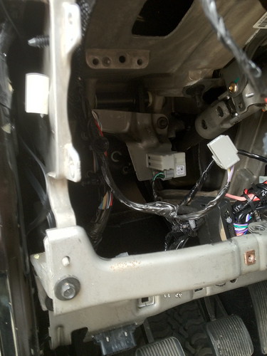
The location of the Infinity amp is behind the drivers kick panel. There is no need to remove the amp to gain access to the wiring, but I wanted a good look, so I took it out.
IMG_1501 by imedic31, on Flickr
IMG_1482 by imedic31, on Flickr
IMG_1486 by imedic31, on Flickr
There are numerous locations to access the OEM wiring, but I liked the idea of being close to the source, and an easy 12v power tap.
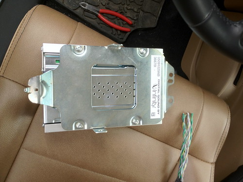
There are two connectors on the bottom of the Infinity amp. One is an input connector (White 22Pin), getting audio from H/U, power, Canbus signal, etc.
The other connector (Black 16 Pin) contains all of the output audio signals, EXCEPT front tweeter signals. These tweeter signals come from the "input" connector, presumably just a simple passthrough, as there isn't much power required to drive a tweeter.
IMG_1484 by imedic31, on Flickr
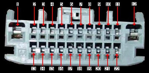
22 pin amplifier supplyLARGE by imedic31, on Flickr
The above 22 pin connector is the Amps 'Input'. Both the 22Pin and 16Pin connectors plug into the 'bottom' of the amp, when the amp is installed in it's location.
22PinListSpeaker by imedic31, on Flickr
16 pin amplifier out by imedic31, on Flickr
16PinListing by imedic31, on Flickr
Pinout listing for both - colors and pin #'s confirmed to be 100% accurate for a 2011 Sahara Unlimited.
Just for Info Purposes:
VidNavInterconnect by imedic31, on Flickr
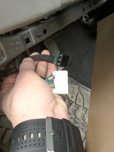
To make things easier for me, I pre-spliced my connections (speaker level inputs) into the Kicker Sum/LOC. When I was comfortable enough that I had the correct wiring harness, and that everything matched up, I clipped the OEM amps output wiring, ensuring I had plenty of wire left. I wired this 16Pin connector to my pre-made connections feeding the kicker, and that was all it took. Plug the harness back into the OEM Amp, and my speaker level inputs are complete. Almost. lol..
IMG_1488 by imedic31, on Flickr
IMG_1490 by imedic31, on Flickr
Now attaching my pre-made connections to my kicker Sum/Loc... nicely taped and bundled for easier handling..
IMG_1494 by imedic31, on Flickr
Going back to the 22Pin connector (White one above) you'll notice the two OEM tweeter feeds 'leaving' the OEM Amp 'Input' connector to feed the tweeters. Splicing into the wiring allows me to connect that signal / channel as well, ensuring that I am not missing any OEM signal.
Now that we have our audio source done, we need to provide power to the Kicker Sum/LOC AND the aftermarket amp. There is a temptation to tap the cigarette lighter or the 12v accessory plug. I'd suggest you didn't. They used to be very appropriate 12v constant sources in older vehicles, but with TIPM's and whatnot nowadays, I'd just leave them. Your best option is to provide a stand alone 12v source, directly from the battery. This is the safest and most reliable method, and you can (should) use an inline fuse to prevent damage to your aftermarket equipment (and your vehicle for that matter.)
I ran my 12v power cable through an existing grommet in the firewall. The only thing that goes through there is the rear wiper washer fluid supply hose. I left the wire shielding off for the moment to help see it (Blue). Anytime you run wiring through an engine compartment, it should be protected from the heat and other road elements by using some type of wrap or shielding.
IMG_1495 by imedic31, on Flickr
From there, I added an inline fuse, and connected to the positive terminal of my battery. Try to position the fuse as close as possible to the battery... if something causes a short, the fuse blows, and eliminates power to the entire line. Your short / fault would need to occur nearly right at the battery in order to cause fire / damage. It also allows easy access to the fuse should it ever happen to blow.
IMG_1497 by imedic31, on Flickr
IMG_1499 by imedic31, on Flickr
Another fuse note... leave it out until you are finished connecting everything. No reason to make your line 'live' while farting around with the wiring.
So... Now we have our audio source, our power, and grounds (There are a bazillion grounding locations in the Jeep...Find the closest one for your preference) Now we need to upgrade those POS OEM speakers.
The rear overhead pods are a no brainer, so I won't say much about them. BUT... here is a pick after OEM speakers removed, and voids filled with polyfill.
5$ at walmart... will reduce the tinny or hollow sounding speaker bar.
Polyfill by imedic31, on Flickr
IMG_1282 by imedic31, on Flickr
IMG_1287 by imedic31, on Flickr
As you have probably read on here before, the front speaker pods are a PITA!!!
Anyway, I found it easier to take them right out, make connections, stuff with polyfill, replace OEM POS speakers, and replace into the positions found. On a side note, there are two screws securing the sides, with 7mm heads. There is also on on the bottom attaching the pod to the dash frame. This is a 10mm head, or you can use a hex key... cannot recall the size atm...
IMG_1503 by imedic31, on Flickr
Definitely easier to manage with pod removed.
IMG_1502 by imedic31, on Flickr
Now for the tweeters... You may wish to leave them OEM, but WHY? lol. These are a little more adventurous to install, as it involves trimming / enlarging the hole (for my tweeters anyways..). Just be sure to take your time, measure, fit, cut, fit, cut, measure, fit, etc. Working slowly and by repeatedly checking the fitment, will save you an ugly eyesore (if thats something your into..lol) I used a dremmel, which worked well for me.
IMG_1290 by imedic31, on Flickr
And here is one finished. That dash material gets friggin everywhere... just so you know..
IMG_1291 by imedic31, on Flickr
The passenger side front speaker and tweeter are duplicates of the driver side... although there is less free play in the dash to move things around. I found that unbolting the side screws, then the bottom one for the speaker pod, and turning the pod 90 Deg counter clockwise made it super easy to remove the pod through the glove compartment opening. (Glove comp. removed of course...)
Sooooo... That about wraps it up. The rest is pretty easy to move through, like running your wires, finding grounds, etc, so they are not touched on in this write up. I replaced all of the OEM speaker wire with new stuff. I also put in a splitter off of my main 12v battery source. One to the Kicker, and one to the Alpine amp.
IMG_1500 by imedic31, on Flickr
Also, here are a few more pics of items and their locations...
Bluetooth module:
IMG_1480 by imedic31, on Flickr
And I think this is a Hard Drive, but not 100% sure... (The item with the white barcode on it... the other module in the picture is an iDataLink for my viper alarm/starter..)
IMG_1483 by imedic31, on Flickr
Well, hopefully this is of some use to someone. I've never seen a full write up about this, which is odd.... cause there are hundreds & hundreds of posts asking about this stuff. As for the OEM POS sub, I'll be removing it, and am planning on making the old sub location into a secure storage spot, or just somewhere to keep extra gear / fluids / maybe a tool box. Anyway... happy trailing
Oh - and this system rocks! lol. Crystal clear with top down/off at highway speeds. Giggity!!!
Last edited by imedic31; 04-09-2012 at 11:00 PM. Reason: Adding Links / Fixing broken link

The following 2 users liked this post by imedic31:
Eric2XU (01-16-2018),
Right-Angle (07-29-2019)
 04-09-2012, 02:15 PM
#4
JK Newbie

Join Date: Jan 2008
Location: Branford, CT
Posts: 20
Likes: 0
Received 0 Likes
on
0 Posts
Great writeup, thanks for putting in the time to share!
One suggestion, the tweeter plastic is soft enough to cut with a (sharp) razor knife, less mess than using a dremel.
One question - you said you replaced the stock speaker wires, what about the front speaker pods?
I only replaced the connectors inside the pods with radio shack quick disconnects - pretty sure I got the polarity right, used green as positive and black as negative.
04-09-2012, 02:44 PM
#5
JK Newbie
Thread Starter
Great writeup, thanks for putting in the time to share!
One suggestion, the tweeter plastic is soft enough to cut with a (sharp) razor knife, less mess than using a dremel.
One question - you said you replaced the stock speaker wires, what about the front speaker pods?
I only replaced the connectors inside the pods with radio shack quick disconnects - pretty sure I got the polarity right, used green as positive and black as negative.
One suggestion, the tweeter plastic is soft enough to cut with a (sharp) razor knife, less mess than using a dremel.
One question - you said you replaced the stock speaker wires, what about the front speaker pods?
I only replaced the connectors inside the pods with radio shack quick disconnects - pretty sure I got the polarity right, used green as positive and black as negative.
MonsterJoe - Great suggestion.. I totally didn't even think of using a knife / blade - probably cause I would have completed the project minus a functional finger..lol. The speaker pod pic shows the OEM wiring, you are correct. Before I re-installed I decided to switch it out for new stuff, and forgot to take another picture.
Chronotripper - unfortunately no, I was too excited to start the project to take sound examples prior to diving in... which is ok, as there is no real way to appreciate the sound differences between pre/post soundstage in a video, it just wouldn't do it justice.. like going to a concert and taking vid clips... sounds nothing like the real thing. lol
Glad someone liked the writeup!
04-09-2012, 02:45 PM
#6
JK Newbie
Thread Starter
04-09-2012, 06:01 PM
#7
JK Newbie
Join Date: May 2011
Location: Western Mass
Posts: 79
Likes: 0
Received 0 Likes
on
0 Posts
Nice write up any pics of where you installed the new amp or summing loc?
Also the Mopar link has the ... in it instead of the real link
Also the Mopar link has the ... in it instead of the real link
Last edited by cmg; 04-09-2012 at 06:15 PM.
Trending Topics
04-09-2012, 11:07 PM
#9
JK Newbie
Thread Starter
As for the LOC & Amp locations... havn't really decided. At the moment I have the LOC under the drivers seat, and the Amp under the passenger seat. I figured out of sight, out of mind, for those that choose to be on that side of the fence... easily accessable for adjustments when needed, and both sides have a factory grounding pin under each seat. In the end, I'll probably fab some brackets and attach to the underside of the seat, allowing enough room for seat adjustment & ventilation (Class D amp, so no big worries about overheating.)
I'll definitely update the thread with add'l pics once I have completed.
Cheers!
04-10-2012, 06:25 AM
#10
JK Enthusiast
Join Date: May 2011
Location: Irvine, CA
Posts: 113
Likes: 0
Received 0 Likes
on
0 Posts
Great write up! Really good job. 
Your set up is exactly what I plan on doing soon. You made it so much easier for me by putting together all the pinouts and confirming them on a 2011.
Thanks!
Your set up is exactly what I plan on doing soon. You made it so much easier for me by putting together all the pinouts and confirming them on a 2011.
Thanks!