Rubicon Locker By-pass --- Off Road Engineering's kit
 10-06-2012, 11:52 AM
#1
JK Freak
Thread Starter
Here is the kit in all its glory...
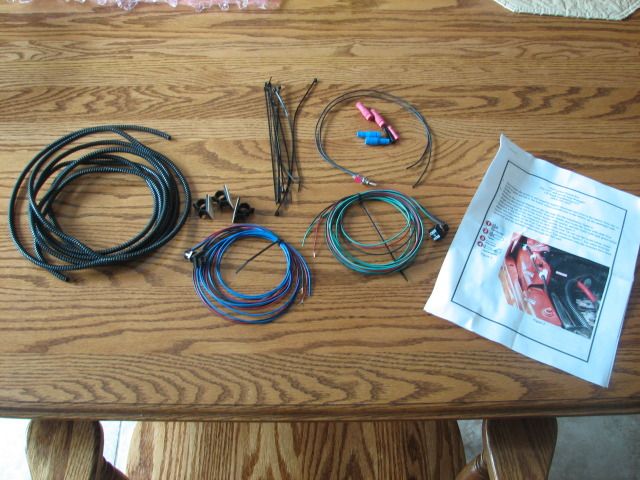
It comes with all of the necessary components to get the lockers operating in any transfer-case range... Two locker witches, a master disable switch, wire, wire loom, zip-ties, wire connectors, and most importantly (for me anyway), directions.
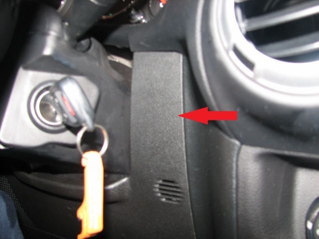
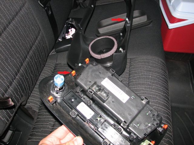
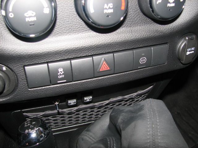
I planned on installing the switches in a discrete location, like in the panel behind the key. But, with the way these switches are set up, they are not really removeable so I decided it would be best to mount them in a location that does not need to be removed very often. This particular panel needs to be removed to get at screws to removed the dash, so I did not go here where I wanted...
The first thing to do is remove the battery.
Then there is the dash removal. This is being done on a 2012 model, so I am not sure about the process on the earlier dashes. There are four screws holding it in place, along with several clips. This panel needs to be tipped down (simply by pulling)...
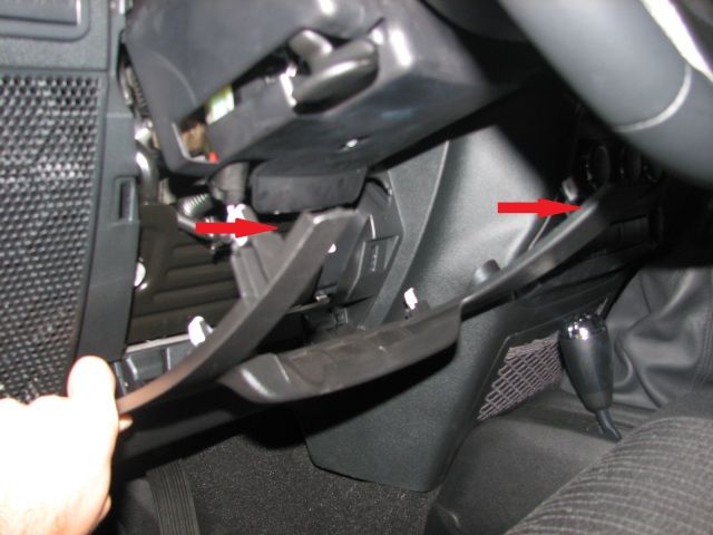
Then remove the two screws at each side of the steering wheel...
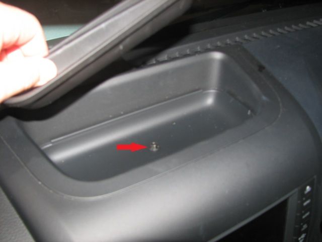
Pull the rubber piece out of the top storage tray to access the screw under it...
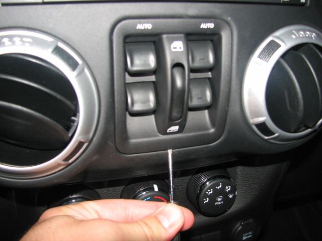
Then pry the window switch out of the dash with a tiny screwdriver...
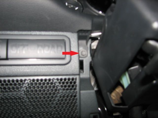
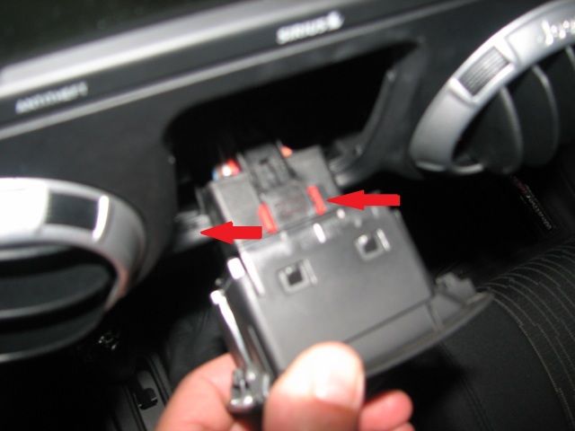
Remove the switch by sliding the red plastic piece to the left...
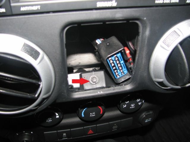
And then pull the switch out to gain access to the screw here...
After those 4 screws are removed, the two main pieces can be removed simply by pulling. There are several small plastic pieces that hold them in place, which are much easier to work with than other ones I have dealt with before...
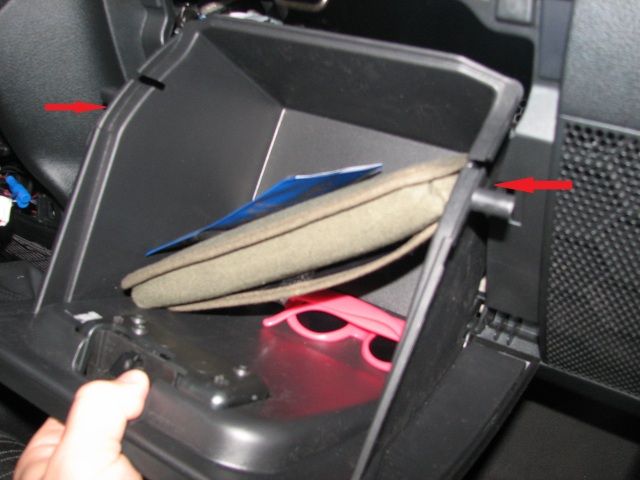
I also pulled the glovebox out too, simply by putting pressure at the sides and tipping down/out...
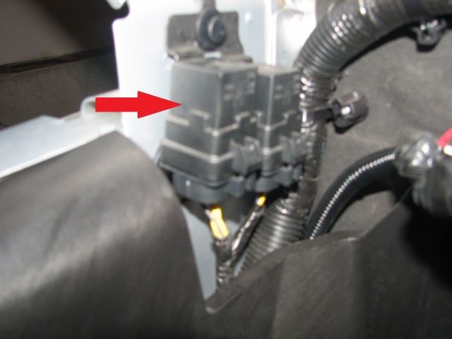
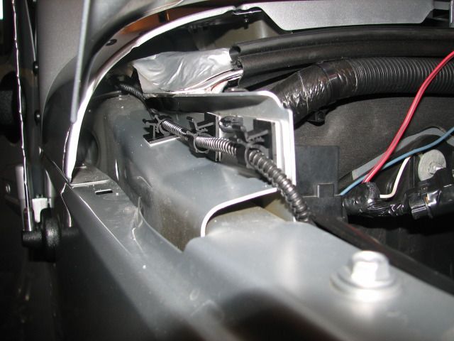
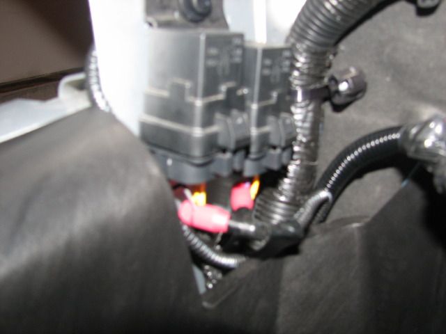
Now its time for some wiring. Locate the locker relays next to the battery, and install the supplied wire connectors onto the proper wires (violet wire with green stripe is rear locker, violet with blue stripe is front locker). Here are the relays...
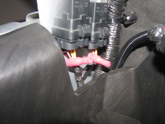
And with the wire connectors installed...
Then drill two 9/16" holes where you want the locker switches, and a 1/4" hole where you want the disable switch. The wires on the disable switch are not very long, so it has to be close to the accessory outlet (you need to tap into the ground and power wires of the accessory outlet). So I put them here...
Then you install the wire connectors on the two wires for the accessory outlet. The two black wires on the locker switches get connected to one wire of the disable switch, then the other wire on the disable switch gets connected to the ground on the accessory outlet. The two red wires for the locker switches get connected to the power wire of the accessory outlet...
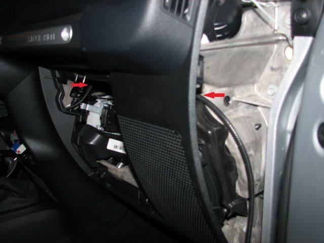
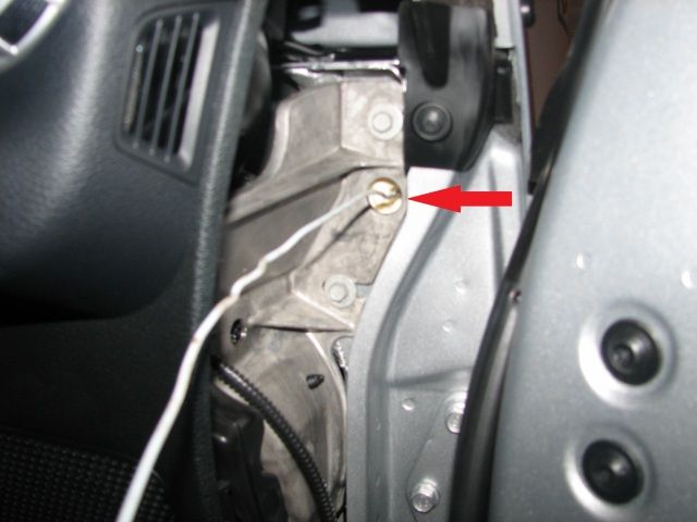
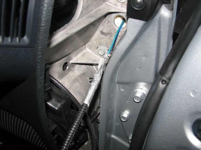
Then you install the other switch wires inside wire loom and route them into the engine compartment. I went across the glovebox area, through a small hole in the firewall, and then onto the side of the fender. I used a coat-hanger to get the wire/loom through the hole, and taped up the connection as it is fairly tight and wants to rip the loom off...
Then connect the wires to the tap connectors that were installed earlier (color cordinated)...
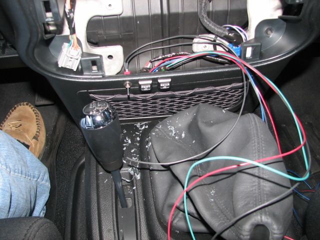
That is basically the jist of it. Now just put everthing back together. Here is my finished product...
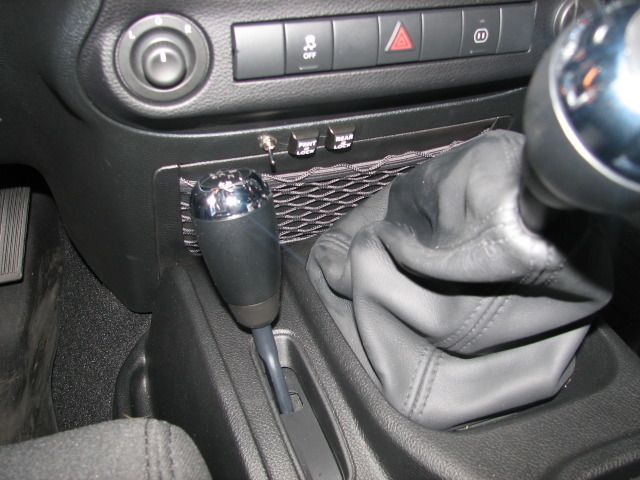
I thought about puting the switches here on this panel (at the spare locations), but it is not really possible as there is one big electric device behind it...
It comes with all of the necessary components to get the lockers operating in any transfer-case range... Two locker witches, a master disable switch, wire, wire loom, zip-ties, wire connectors, and most importantly (for me anyway), directions.
I planned on installing the switches in a discrete location, like in the panel behind the key. But, with the way these switches are set up, they are not really removeable so I decided it would be best to mount them in a location that does not need to be removed very often. This particular panel needs to be removed to get at screws to removed the dash, so I did not go here where I wanted...
The first thing to do is remove the battery.
Then there is the dash removal. This is being done on a 2012 model, so I am not sure about the process on the earlier dashes. There are four screws holding it in place, along with several clips. This panel needs to be tipped down (simply by pulling)...
Then remove the two screws at each side of the steering wheel...
Pull the rubber piece out of the top storage tray to access the screw under it...
Then pry the window switch out of the dash with a tiny screwdriver...
Remove the switch by sliding the red plastic piece to the left...
And then pull the switch out to gain access to the screw here...
After those 4 screws are removed, the two main pieces can be removed simply by pulling. There are several small plastic pieces that hold them in place, which are much easier to work with than other ones I have dealt with before...
I also pulled the glovebox out too, simply by putting pressure at the sides and tipping down/out...
Now its time for some wiring. Locate the locker relays next to the battery, and install the supplied wire connectors onto the proper wires (violet wire with green stripe is rear locker, violet with blue stripe is front locker). Here are the relays...
And with the wire connectors installed...
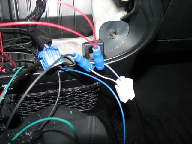
Then drill two 9/16" holes where you want the locker switches, and a 1/4" hole where you want the disable switch. The wires on the disable switch are not very long, so it has to be close to the accessory outlet (you need to tap into the ground and power wires of the accessory outlet). So I put them here...
Then you install the wire connectors on the two wires for the accessory outlet. The two black wires on the locker switches get connected to one wire of the disable switch, then the other wire on the disable switch gets connected to the ground on the accessory outlet. The two red wires for the locker switches get connected to the power wire of the accessory outlet...
Then you install the other switch wires inside wire loom and route them into the engine compartment. I went across the glovebox area, through a small hole in the firewall, and then onto the side of the fender. I used a coat-hanger to get the wire/loom through the hole, and taped up the connection as it is fairly tight and wants to rip the loom off...
Then connect the wires to the tap connectors that were installed earlier (color cordinated)...
That is basically the jist of it. Now just put everthing back together. Here is my finished product...
I thought about puting the switches here on this panel (at the spare locations), but it is not really possible as there is one big electric device behind it...
Last edited by olyelr; 10-06-2012 at 01:41 PM.
 10-06-2012, 03:43 PM
#2
JK Enthusiast
Join Date: Apr 2012
Location: Pittsburgh
Posts: 416
Likes: 0
Received 0 Likes
on
0 Posts
Thanks for the write-up.
Two things made mine a bit easier:
1) There is an existing hole/rubber grommet on the driverside firewall just above the pedals so no drilling, just use wire lume and tie wrap it to the existing wire lume that runs along the top of the firewall.
2) The Daystar switch panel and ARB locker switches, I was able to run the wires over the steering column under the dash and fish the wires up between the consol and floor so I didn't have to remove any of the dash.
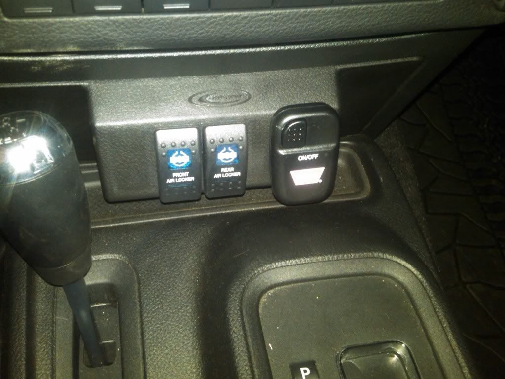
Ya, they say "air" but you get the idea, these also light up without any other special wiring.
Two things made mine a bit easier:
1) There is an existing hole/rubber grommet on the driverside firewall just above the pedals so no drilling, just use wire lume and tie wrap it to the existing wire lume that runs along the top of the firewall.
2) The Daystar switch panel and ARB locker switches, I was able to run the wires over the steering column under the dash and fish the wires up between the consol and floor so I didn't have to remove any of the dash.
Ya, they say "air" but you get the idea, these also light up without any other special wiring.
Last edited by Mschneid; 10-06-2012 at 03:46 PM.
10-06-2012, 04:35 PM
#3
JK Freak
Thread Starter
Thanks for the write-up.
Two things made mine a bit easier:
1) There is an existing hole/rubber grommet on the driverside firewall just above the pedals so no drilling, just use wire lume and tie wrap it to the existing wire lume that runs along the top of the firewall.
2) The Daystar switch panel and ARB locker switches, I was able to run the wires over the steering column under the dash and fish the wires up between the consol and floor so I didn't have to remove any of the dash.
Looks good! If I would have known that little switch holder was available you have I may have got one of those. Not sure if it will fit with a manual trans though, stuff is tight right there. I wonder if the manual trans steels the existing hole you used in the firewall, cause I didnt see one on mine. I originally wanted to go out that side so I didnt have to bother with the dash. The directions showed going out the passenger side hole, so I just used that one. Oh well, its done now!
10-07-2012, 04:29 AM
#4
JK Enthusiast
Join Date: Apr 2012
Location: Pittsburgh
Posts: 416
Likes: 0
Received 0 Likes
on
0 Posts
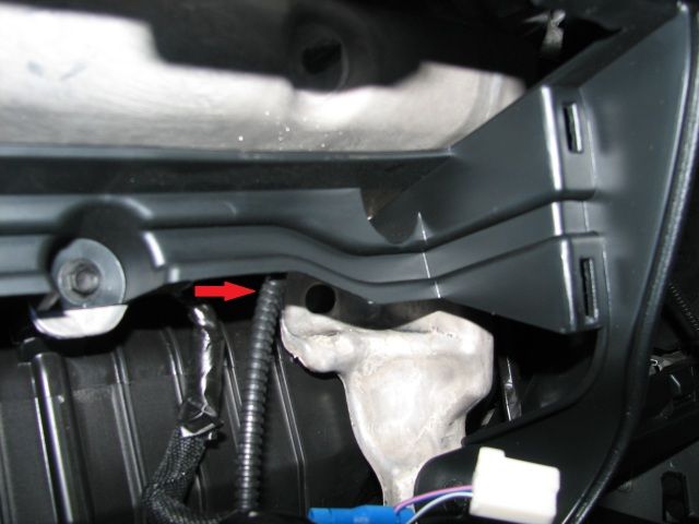
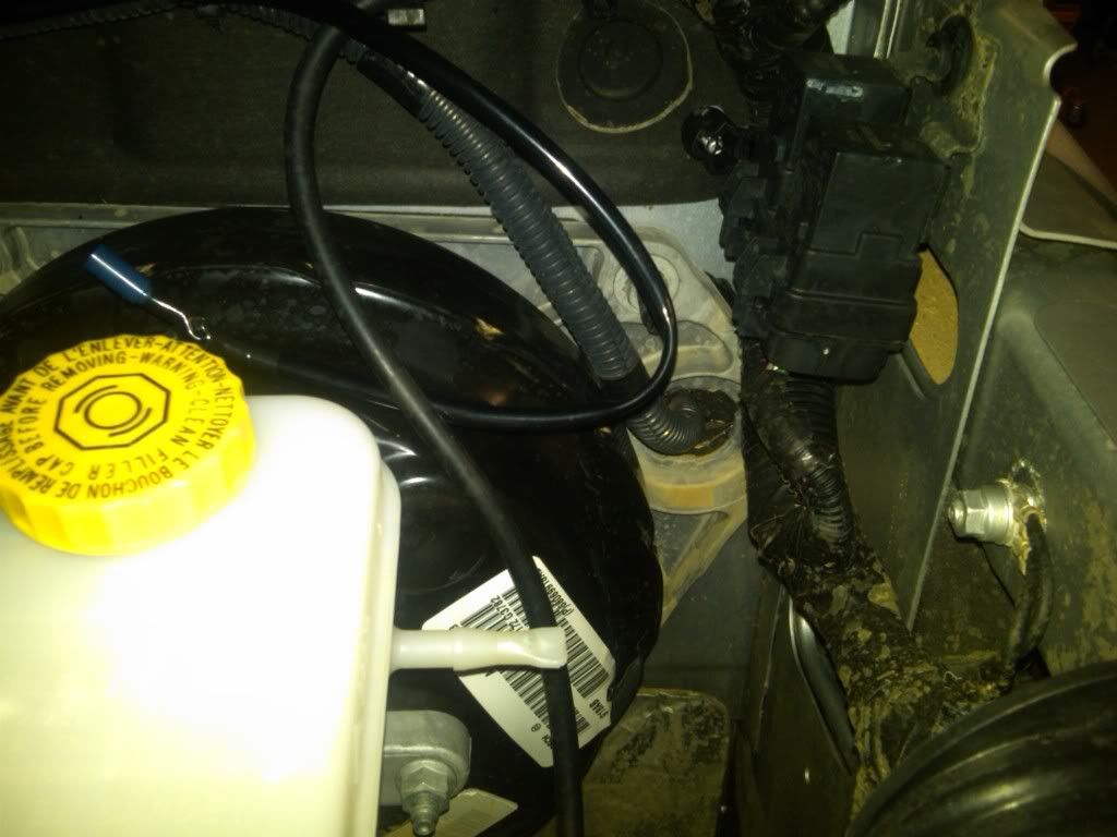
Here is the hole I ran my lume through the firewall, right of the brake booster.
The switch plate is around $20 and the switches were $10 each if I remember, that switch plate goes in place of the net on the consol an can hold up to 5 switches. the lume is cheap at Harbor Freight or Trader Horn (local to me).
The switch plate is around $20 and the switches were $10 each if I remember, that switch plate goes in place of the net on the consol an can hold up to 5 switches. the lume is cheap at Harbor Freight or Trader Horn (local to me).
Last edited by Mschneid; 10-07-2012 at 04:32 AM.
10-10-2012, 03:36 AM
#5
JK Freak
Thread Starter
Well, I havnt done any real word testing yet as I have not even left the driveway with the Jeep this week. But, I backed it out of the garage and tested them in 2 high and both worked without a doubt so I must have done something right. Also, the switches light up when they are on (not sure about when they are off and the headlights lights are on?), and the locker lights on the dash blink when they are engaged.
10-10-2012, 05:18 AM
#7
JK Enthusiast
Join Date: Apr 2012
Location: Pittsburgh
Posts: 416
Likes: 0
Received 0 Likes
on
0 Posts
Trending Topics
10-10-2012, 05:20 AM
#8
JK Enthusiast

Join Date: Oct 2012
Location: York, Pa
Posts: 105
Likes: 0
Received 0 Likes
on
0 Posts
Ok this may sound like a dumb question but I'm confused as to what the purpose is of this kit. I assume that the kit gives you the option of locking one axel or the other individually as opposed to the factory button on the dash locks both at the same time?
10-10-2012, 05:44 AM
#9
JK Jedi Master
Normally, they can be locked only in 4lo, rear first, then front.
Last edited by ronjenx; 10-10-2012 at 05:58 AM. Reason: spelling
10-10-2012, 05:49 AM
#10
JK Enthusiast
Join Date: Oct 2012
Location: York, Pa
Posts: 105
Likes: 0
Received 0 Likes
on
0 Posts
Originally Posted by ronjenx
This mod give the opportunity to lock either axle, anytime you want. It's up to the user to know when NOT to lock the axles.
Normally, they can be locked only in 4lo, rear first, then front.