HID sealed projector retrofit
 12-21-2018, 11:51 AM
#1
Super Moderator

Thread Starter
New project! I'm going to document it here for your enjoyment because I think it's really the road less traveled. Quick review of the journey to this point:
- Stock headlights suck. I think there's a general consensus there.
- I went with the JK edition JW Speakers first and I wasn't thrilled. I thought the color distribution was mediocre and the overall output was just good. The pattern was decent I think. I wasn't satisfied.
- I tried Inspired Engineering's set. I liked the color better and it seemed to be a more even distribution, but there was no cutoff and the output, again, was just ok. I do like how the LEDs sit in straight lines and the DRL and signal switchbacks are cool. Still looking for better light though.
I've done HID retrofits on all my motorcycles and I think the light output of a bi-xenon projector is still the best you can get. I looked at a standard projector retrofit on the JK lamp, but the projector is too long and would require a ton of work to get to properly fit. I don't like doing JB Weld hack jobs so I held off.
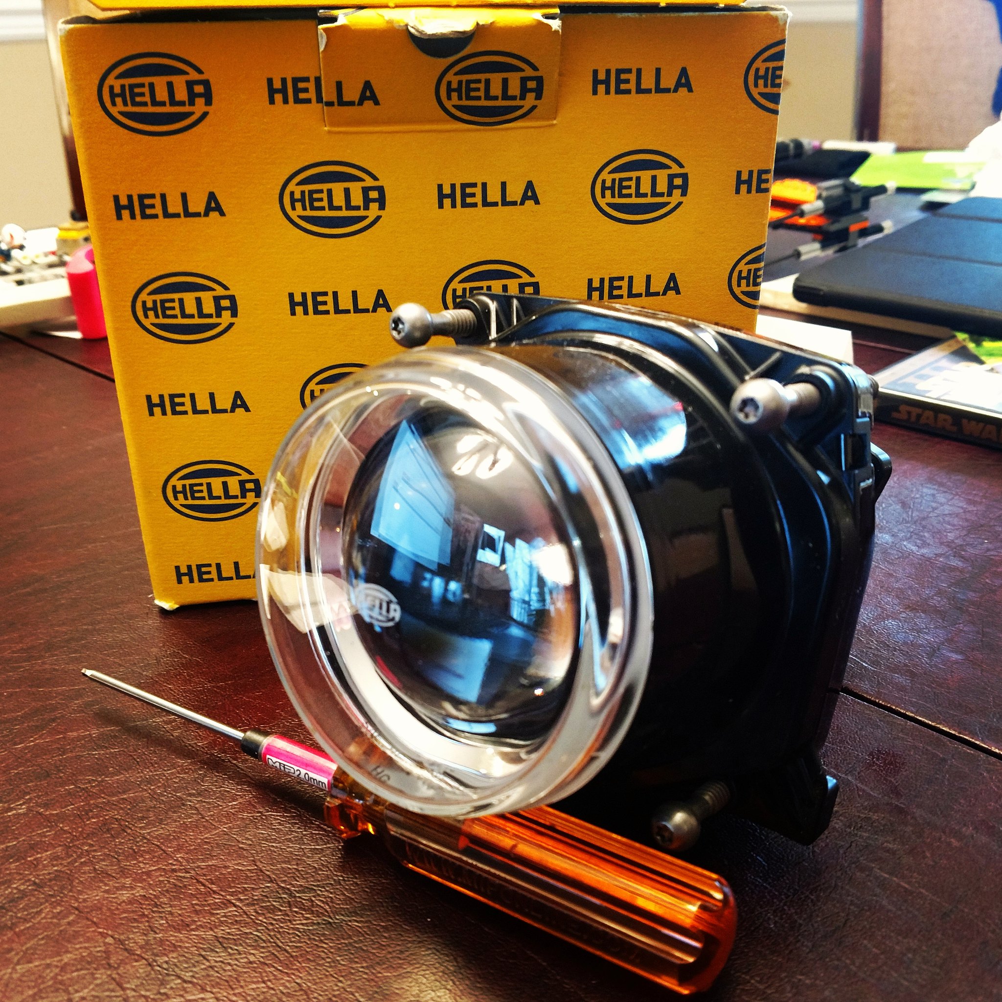
I found Hella's sealed projectors a looong time ago but they were ABSURDLY expensive. And that's saying something coming from me! They were available on Amazon so I put them in my wish list, the place where things go so I remember them a year later and break down and impulse buy them. I looked again recently and they were much more reasonably priced so I pulled the trigger. These things look AWESOME. Totally waterproof housing for the projector, nothing else required. I could zip tie one to the roof rack and never have any trouble.
The plan is the same as a motorcycle retrofit. Design and fab a mounting bracket and housing. We're still in the early stages as they just came in, so I'm not sure on the specifics yet. The projector comes with adjustment screws so the stock ones in the jeep headlight mounting rings are not necessarily required. I may keep the rings and mount to them for a good fit or I may mount directly to the headlight bucket sheet metal. I may do the mounting bracket in high temp PETG or I may have it waterjet cut from steel or aluminum. I'll do some investigation into what kind of heat comes off this projector. When the mounting is settled, I want to design some sort of shroud to fill the headlight hole, make it look nice and hide the mounting bracket. I haven't decided on any specifics for this yet either, I'm trying to account for rain, snow, heat, mud, etc. and come up with something that looks good and works. It's a process.
I'll update here as I progress. I'm looking forward to some outstanding light. Here's what I'm starting with:
- Stock headlights suck. I think there's a general consensus there.
- I went with the JK edition JW Speakers first and I wasn't thrilled. I thought the color distribution was mediocre and the overall output was just good. The pattern was decent I think. I wasn't satisfied.
- I tried Inspired Engineering's set. I liked the color better and it seemed to be a more even distribution, but there was no cutoff and the output, again, was just ok. I do like how the LEDs sit in straight lines and the DRL and signal switchbacks are cool. Still looking for better light though.
I've done HID retrofits on all my motorcycles and I think the light output of a bi-xenon projector is still the best you can get. I looked at a standard projector retrofit on the JK lamp, but the projector is too long and would require a ton of work to get to properly fit. I don't like doing JB Weld hack jobs so I held off.
I found Hella's sealed projectors a looong time ago but they were ABSURDLY expensive. And that's saying something coming from me! They were available on Amazon so I put them in my wish list, the place where things go so I remember them a year later and break down and impulse buy them. I looked again recently and they were much more reasonably priced so I pulled the trigger. These things look AWESOME. Totally waterproof housing for the projector, nothing else required. I could zip tie one to the roof rack and never have any trouble.
The plan is the same as a motorcycle retrofit. Design and fab a mounting bracket and housing. We're still in the early stages as they just came in, so I'm not sure on the specifics yet. The projector comes with adjustment screws so the stock ones in the jeep headlight mounting rings are not necessarily required. I may keep the rings and mount to them for a good fit or I may mount directly to the headlight bucket sheet metal. I may do the mounting bracket in high temp PETG or I may have it waterjet cut from steel or aluminum. I'll do some investigation into what kind of heat comes off this projector. When the mounting is settled, I want to design some sort of shroud to fill the headlight hole, make it look nice and hide the mounting bracket. I haven't decided on any specifics for this yet either, I'm trying to account for rain, snow, heat, mud, etc. and come up with something that looks good and works. It's a process.
I'll update here as I progress. I'm looking forward to some outstanding light. Here's what I'm starting with:
 12-21-2018, 12:17 PM
#2
JK Jedi
Subscribed. Curious to see how this turns out!
01-25-2019, 03:35 PM
#3
Super Moderator
Thread Starter
Ok! finally found some time today to get started. First thing's first, disassembly and loads of measuring. For those of you who don't know me, I'm heavy on the pictures and heavy on the text so buckle up.
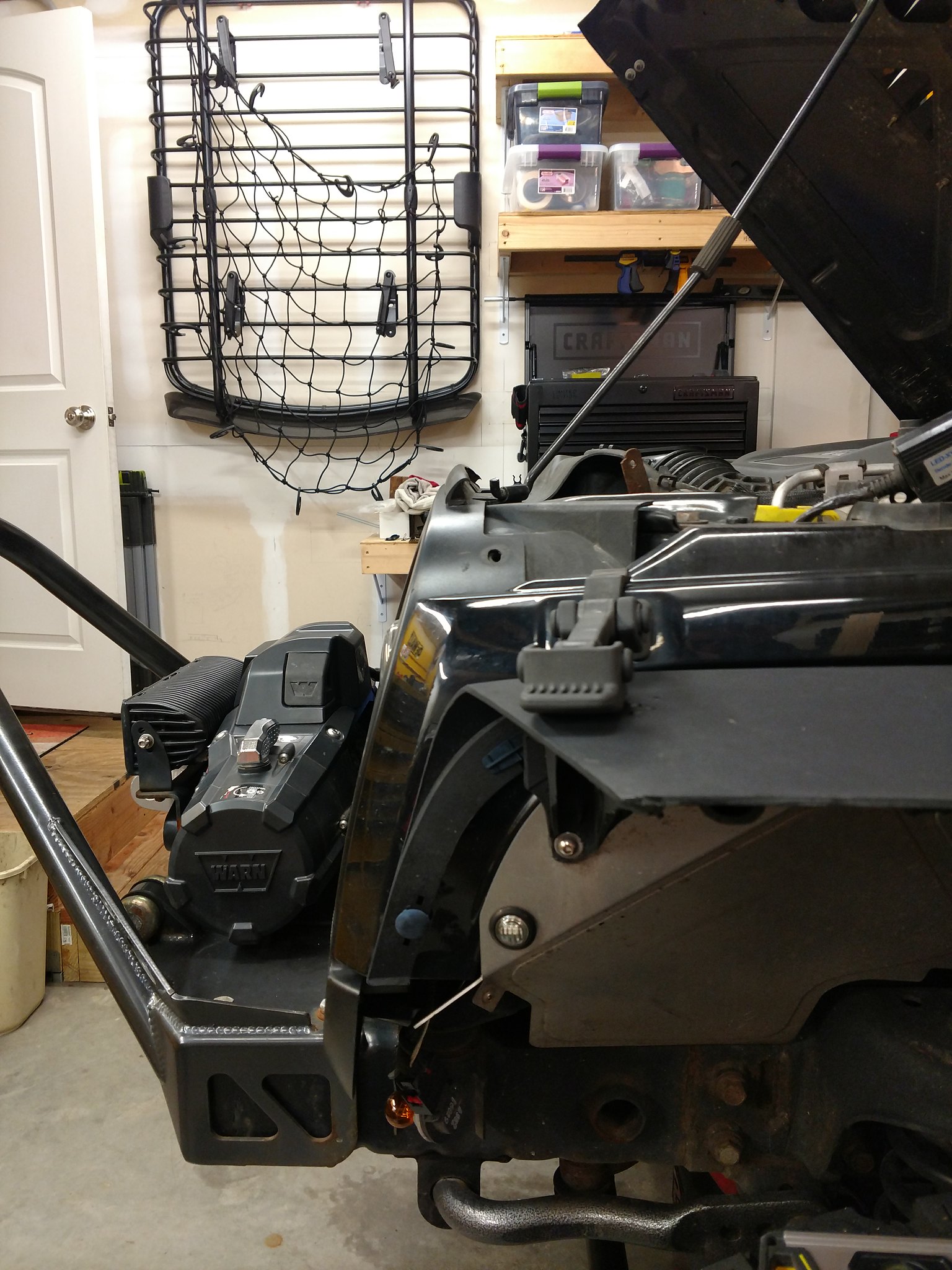
Unbolted the winch, pulled the grill, yanked the headlights and adjustment rings. This is what you're left with:
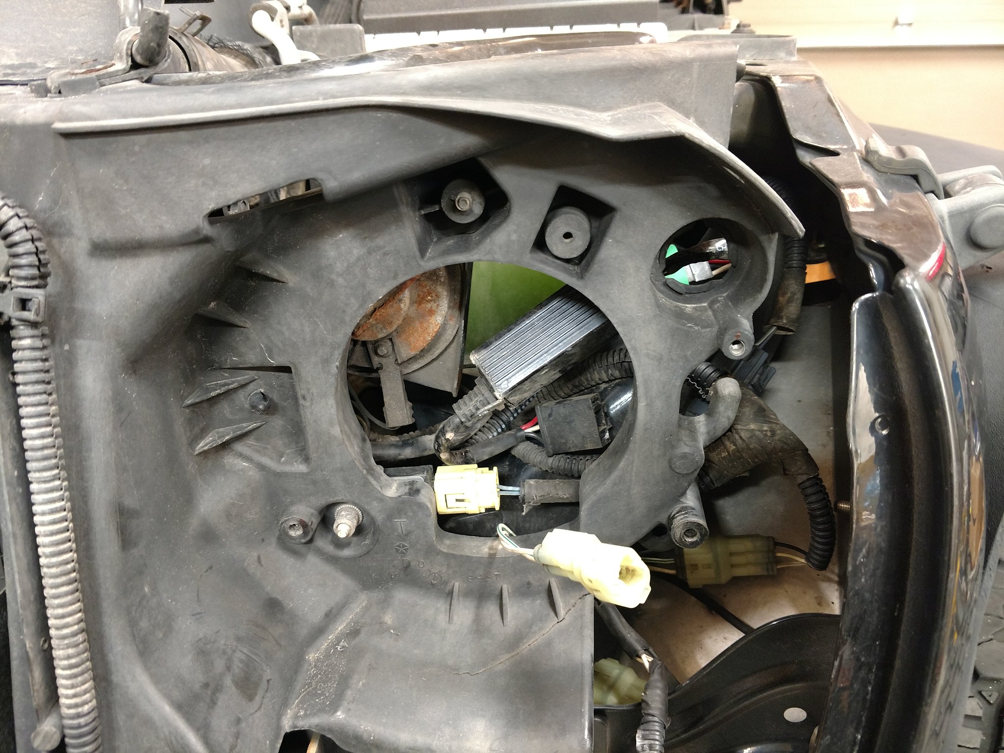
Some of those connectors are for the LED headlights and signals/running lights that are in there now. The stock connector is much simpler. The main thing to take away here is that the three stock bungs for the adjustment screws and the mounting screw are all accessible and, gloriously, seem to share one plane. This means I can get away with a flat bracket that will mount to all three points. That's a plus with both a 3D printed bracket or an aluminum one cut on the waterjet, which are my reliable options. I did recently purchase a dual extruder print head so I potentially have the ability to print any fool shape with dissolvable support, but it's still in the box and I want to get this done.
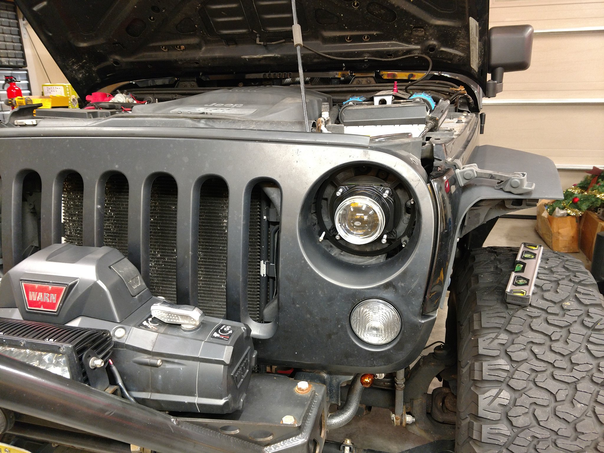
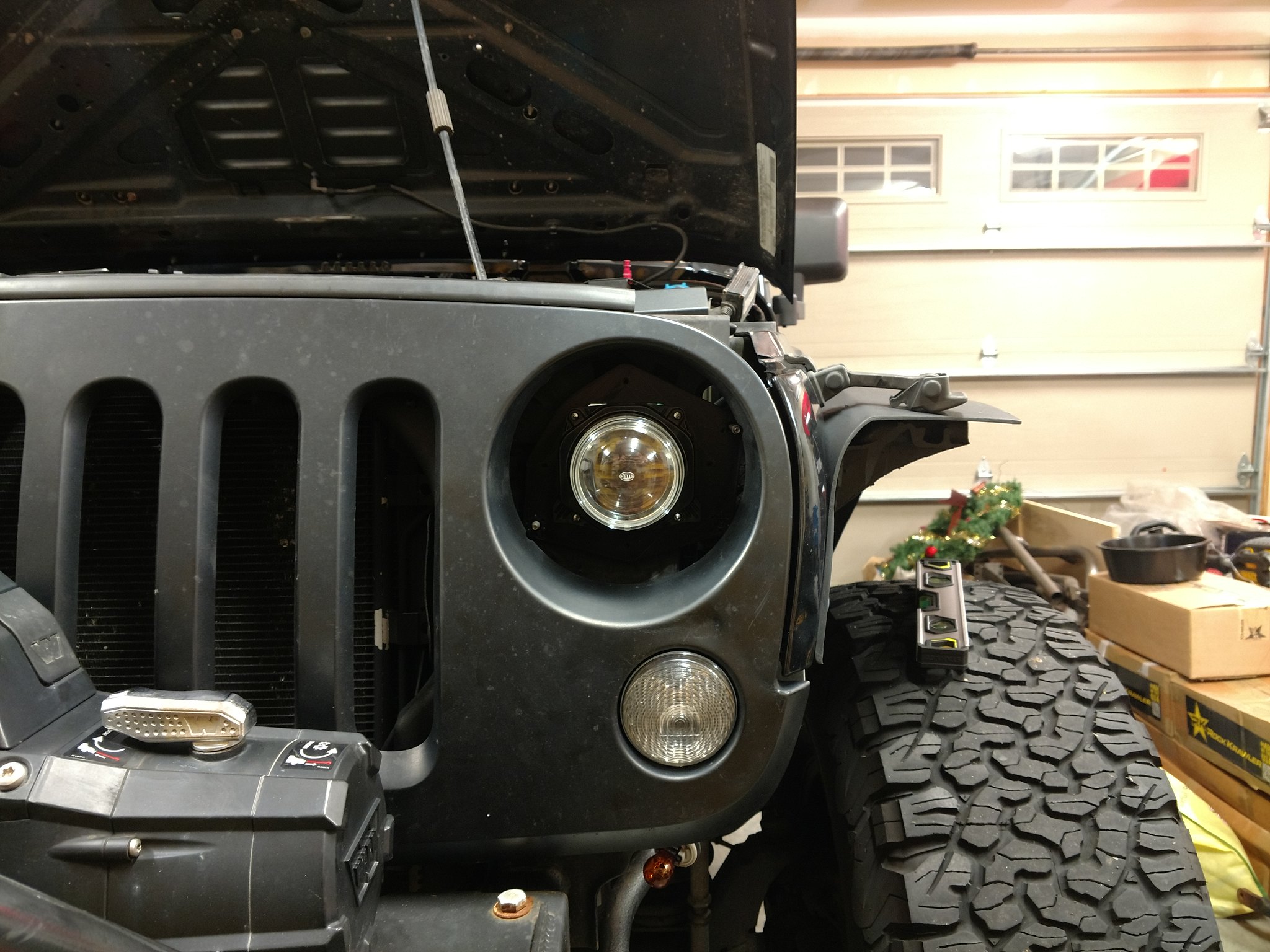
Then a quick and dirty test fit, to make sure I haven't just wasted a whole bunch of money because I didn't plan on the depth of these sealed projectors. They are deeeeep. This deep:

Yeah that's deep. Still,

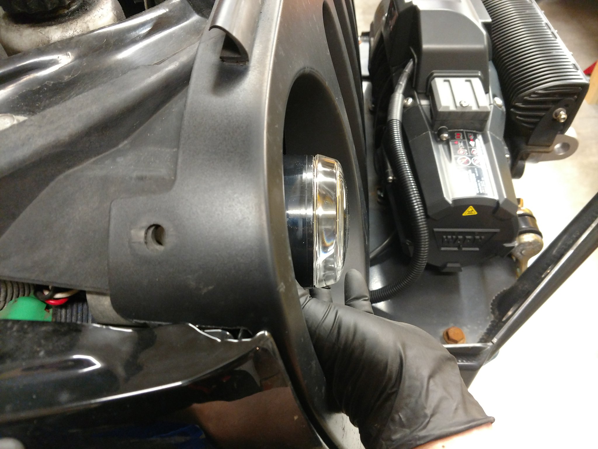
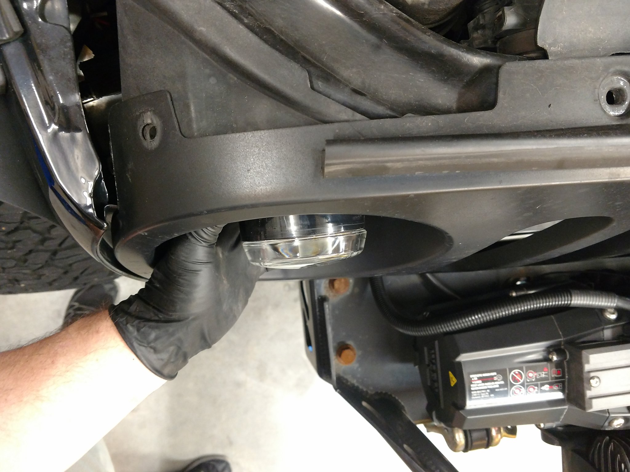
This is about as far back as I can fit them without moving Jeep guts around. I'll probably have to move the horn on the driver side but that's no biggie. There's a wire loom on the passenger side that I'd really rather not mess with. Having them out this far will definitely eliminate any shadowing from the grill light buckets and I'm free to print any design around them to make it look right. At this point I'm cool with that location and I'm moving on.
Next is measuring. Measure, measure, measure. I like to measure several times, with different instruments if at all possible. Things are rarely flat enough and without obstruction to allow me to just put a ruler on them. You can get an idea of what I'm looking for here:
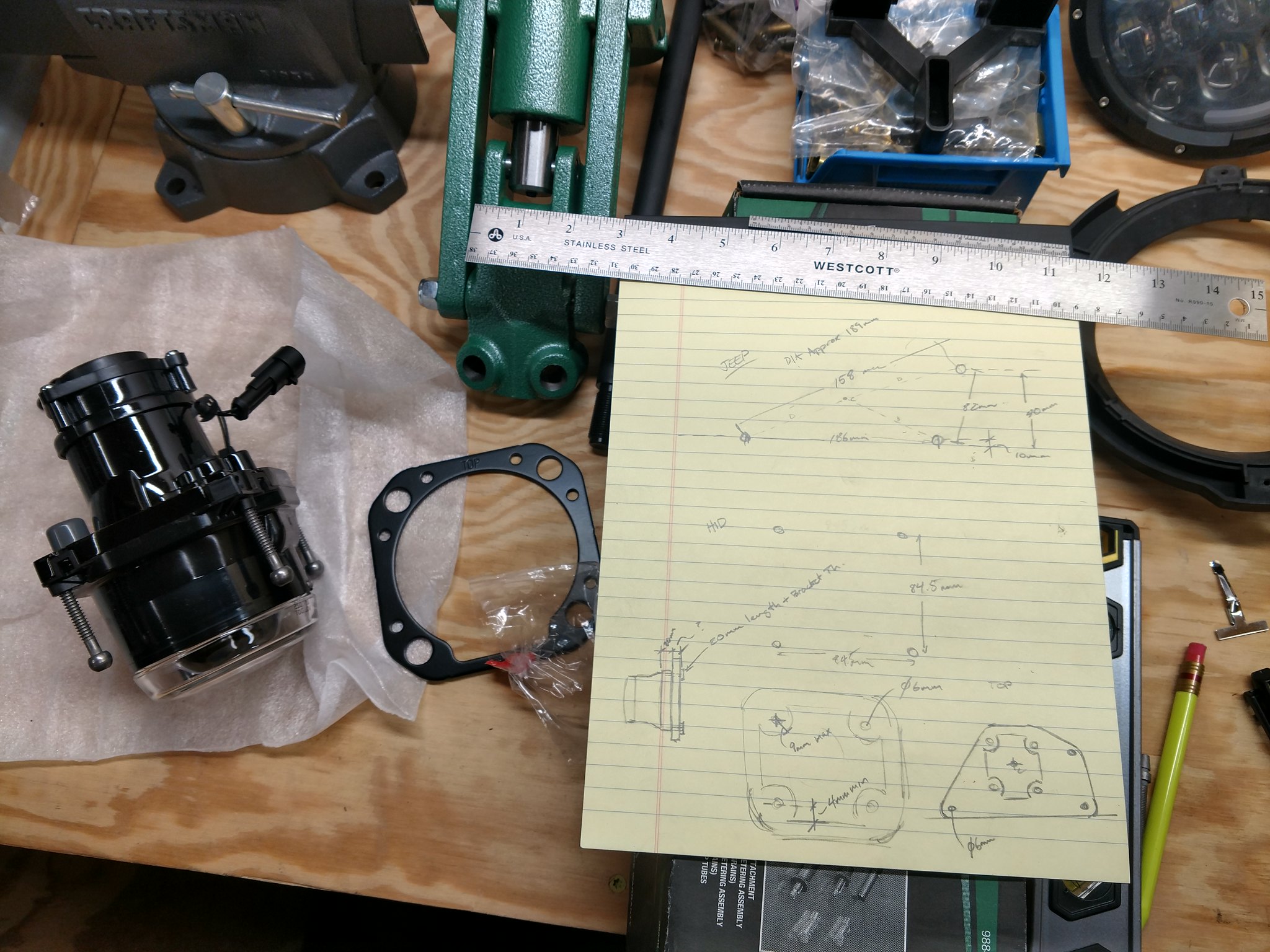
The top is the Jeep headlight bucket hole layout. Middle is the projector and the bottom is me fleshing out a bracket shape. The good news is that so far there's no major interference. The bad news is that, like all things worth doing, all of these parts will not go together the way each of the manufacturers intended. The projectors use a mounting bracket in front of the flange, by the lens, that's held on by those ball end adjuster screws you can see in the pictures above. That's not going to work for me as I need to mount my bracket behind the flange, for bracket simplicity and keeping the projector buried as far inboard as possible. The plastic adjuster screw threads are molded into part of the housing of the projector so I'll be using them one way or another. The bottom drawing shows how I'll make the bracket catch the projector mounting holes while keeping clearance for all the stuff that's on the back of that flange. I'll bolt that in from the back through my bracket and use the jeep screw locations for adjustment, similar to stock. I'd definitely have preferred Hella's adjustment screws but that's just going to complicate things. I guess I could make a thin steel bracket similar to theirs with wider spaced holes and make some aluminum tube stand offs to a rear bracket but.. I'll keep it simple if I can. Using the Jeep adjustment screws means I'll be printing holes for them to spin in, like in the stock mounting rings, or if I make an aluminum bracket I'll need inserts. I'll probably look into both, we're still very preliminary here.
Next up is laying all this out in Fusion 360 and printing a fit template to fine tune all my hacky measuring. I'll go through one to four or five fit templates getting it right, depending on how challenging the measuring was. Once the holes are all lined up I'll do a "proof of concept" which will basically be a full thickness bracket to mount the projector to the Jeep and see that everything will actually fit and stay in place. At that point I have to decide if I'm sticking with a printed bracket or if I'm sending my order to Mr. Waterjet, which will also dictate how I'm hooking up to the adjustment screws. I need at least one new screw too, I bent one driving into an iced-over "water obstacle" at Rausch. The Jeep won some, the ice won some. After that I'm going to design a shroud that will just screw into the mounting bracket. Something to cover the empty space and look cool. I'll leave holes strategically to allow for adjustment without disassembly. If anyone has any ideas on what a functional design might be, I'm all ears. My criteria right now are that it shouldn't hold water, shouldn't let an excess of water through while driving in the rain, shouldn't gunk up too badly in the mud and, optimistically, shouldn't pack with snow. I haven't thought about what that might look like, but I'm excited to see what I come up with.
That's where we stand now, I'm cranking up F360 to start laying it out. Hopefully I'll have more updates soon because the jeep is blind right now and it's my favorite thing to drive.
Unbolted the winch, pulled the grill, yanked the headlights and adjustment rings. This is what you're left with:
Some of those connectors are for the LED headlights and signals/running lights that are in there now. The stock connector is much simpler. The main thing to take away here is that the three stock bungs for the adjustment screws and the mounting screw are all accessible and, gloriously, seem to share one plane. This means I can get away with a flat bracket that will mount to all three points. That's a plus with both a 3D printed bracket or an aluminum one cut on the waterjet, which are my reliable options. I did recently purchase a dual extruder print head so I potentially have the ability to print any fool shape with dissolvable support, but it's still in the box and I want to get this done.
Then a quick and dirty test fit, to make sure I haven't just wasted a whole bunch of money because I didn't plan on the depth of these sealed projectors. They are deeeeep. This deep:
Yeah that's deep. Still,
This is about as far back as I can fit them without moving Jeep guts around. I'll probably have to move the horn on the driver side but that's no biggie. There's a wire loom on the passenger side that I'd really rather not mess with. Having them out this far will definitely eliminate any shadowing from the grill light buckets and I'm free to print any design around them to make it look right. At this point I'm cool with that location and I'm moving on.
Next is measuring. Measure, measure, measure. I like to measure several times, with different instruments if at all possible. Things are rarely flat enough and without obstruction to allow me to just put a ruler on them. You can get an idea of what I'm looking for here:
The top is the Jeep headlight bucket hole layout. Middle is the projector and the bottom is me fleshing out a bracket shape. The good news is that so far there's no major interference. The bad news is that, like all things worth doing, all of these parts will not go together the way each of the manufacturers intended. The projectors use a mounting bracket in front of the flange, by the lens, that's held on by those ball end adjuster screws you can see in the pictures above. That's not going to work for me as I need to mount my bracket behind the flange, for bracket simplicity and keeping the projector buried as far inboard as possible. The plastic adjuster screw threads are molded into part of the housing of the projector so I'll be using them one way or another. The bottom drawing shows how I'll make the bracket catch the projector mounting holes while keeping clearance for all the stuff that's on the back of that flange. I'll bolt that in from the back through my bracket and use the jeep screw locations for adjustment, similar to stock. I'd definitely have preferred Hella's adjustment screws but that's just going to complicate things. I guess I could make a thin steel bracket similar to theirs with wider spaced holes and make some aluminum tube stand offs to a rear bracket but.. I'll keep it simple if I can. Using the Jeep adjustment screws means I'll be printing holes for them to spin in, like in the stock mounting rings, or if I make an aluminum bracket I'll need inserts. I'll probably look into both, we're still very preliminary here.
Next up is laying all this out in Fusion 360 and printing a fit template to fine tune all my hacky measuring. I'll go through one to four or five fit templates getting it right, depending on how challenging the measuring was. Once the holes are all lined up I'll do a "proof of concept" which will basically be a full thickness bracket to mount the projector to the Jeep and see that everything will actually fit and stay in place. At that point I have to decide if I'm sticking with a printed bracket or if I'm sending my order to Mr. Waterjet, which will also dictate how I'm hooking up to the adjustment screws. I need at least one new screw too, I bent one driving into an iced-over "water obstacle" at Rausch. The Jeep won some, the ice won some. After that I'm going to design a shroud that will just screw into the mounting bracket. Something to cover the empty space and look cool. I'll leave holes strategically to allow for adjustment without disassembly. If anyone has any ideas on what a functional design might be, I'm all ears. My criteria right now are that it shouldn't hold water, shouldn't let an excess of water through while driving in the rain, shouldn't gunk up too badly in the mud and, optimistically, shouldn't pack with snow. I haven't thought about what that might look like, but I'm excited to see what I come up with.
That's where we stand now, I'm cranking up F360 to start laying it out. Hopefully I'll have more updates soon because the jeep is blind right now and it's my favorite thing to drive.
01-26-2019, 02:49 PM
#4
Super Moderator
Thread Starter
A quick update for fun, I'm up to fit template version 2. I fine tuned the hole sizes and positions so hopefully it will all line up when this one is done printing. The printer is cranking away, it's one of the happiest sounds there is.
01-28-2019, 03:39 PM
#5
Super Moderator
Thread Starter
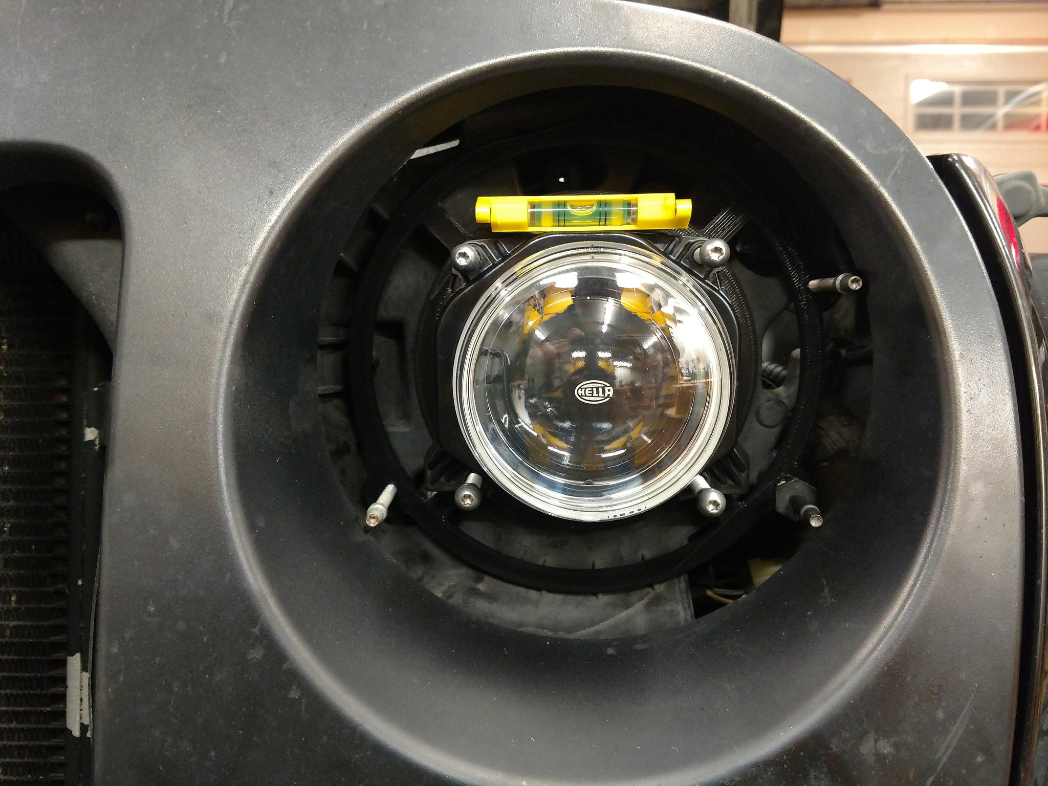
The bracket is evolving. Everything is in place, level, centered and looking good.
Depth from the side:
I really want to use the Hella adjustment screws in the stock screw holes, but they would have to be drilled out and rethreaded for the larger bolts. I doubt I'll be coming back from the HIDs but I think it's always best to leave that option open. Maybe I'll see what I can do to either source some better adjustment screws with the same thread or figure out a way to use the stockers. I just don't like how they've broken through the stock snap-in holes on a few occasions. That would definitely be a weak point on a printed part. I'll figure something out.
01-28-2019, 04:27 PM
#6
JK Jedi
Amazing what you can accomplish with a simple 3D printer. If I'm understanding correctly, you're planning to print some bezel to take up all the space around the light itself?
01-29-2019, 01:30 PM
#7
Super Moderator
Thread Starter
I've been hunting down hardware to mount the projector to the bracket and the bracket to the jeep. I'm limited to matching the stock adjustment screw threads and, less precisely, the threading on the Hella adjustment screw inserts. Those I can probably bully into a similar thread since the size and pitch they used is hard to come by. The inserts are meant to just be cut with the threads of the bolt you put in and they used an extra coarse bolt to make each adjustment turn count for more. I'm pretty sure I'll be making my own setup for the actual adjusting screws because there is no solution that exists that satisfies all my criteria.
Trending Topics
01-30-2019, 07:35 PM
#8
Super Moderator
Thread Starter
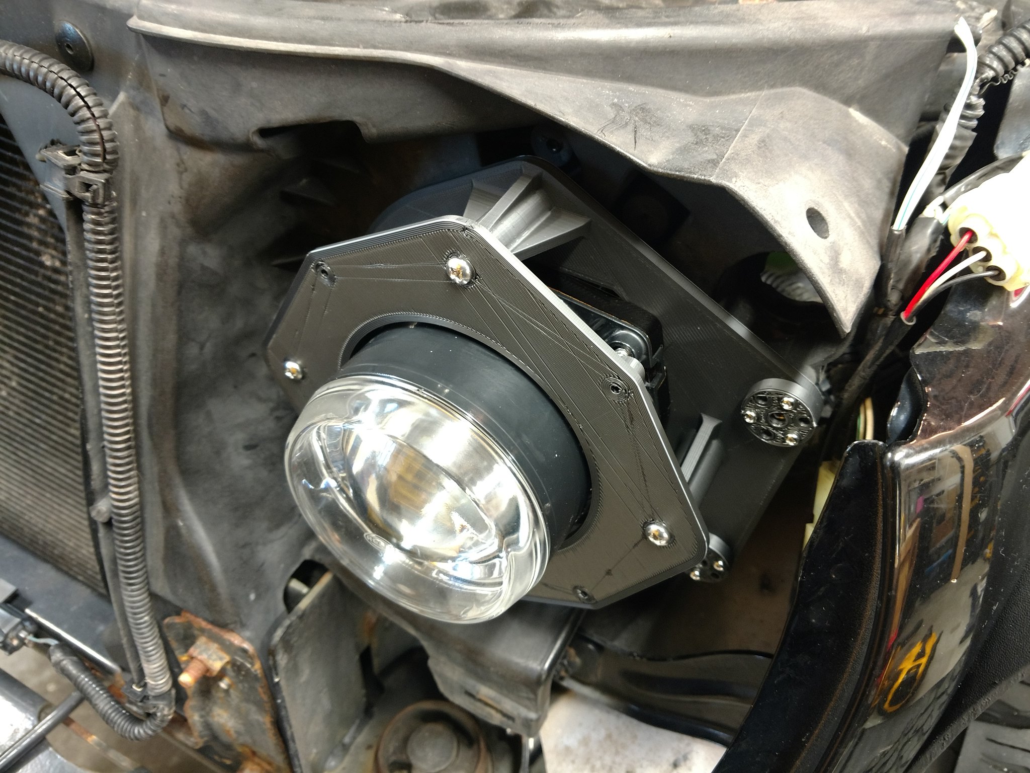
Ooook, the first structural prototype is out. Thanks to 4000 fit templates, it's perfect. I mounted the projector in the bracket and popped the whole assembly in the Jeep. Unfortunately I have to wait till tomorrow until the screws come in to test the improvised adjuster setup, but so far I'm very pleased.
I added 4 screw holes to mount the shroud when I figure out how that's going to work. I think next I'll wire it up and mount the ballasts. Might as well make sure everything works, right? While all that's going on I'll keep working out the shroud. For now I'll just come up with some sort of hole-filling plate while I finalize the design and any DRL/signals I'm going to add. I'm just looking forward to not having to drive the dumb pickup every day!
I added 4 screw holes to mount the shroud when I figure out how that's going to work. I think next I'll wire it up and mount the ballasts. Might as well make sure everything works, right? While all that's going on I'll keep working out the shroud. For now I'll just come up with some sort of hole-filling plate while I finalize the design and any DRL/signals I'm going to add. I'm just looking forward to not having to drive the dumb pickup every day!
02-02-2019, 05:46 AM
#9
Super Moderator
Thread Starter
I'm waiting for the brackets to print. This is finished print material and quality so it takes time. Here's a progress pic.
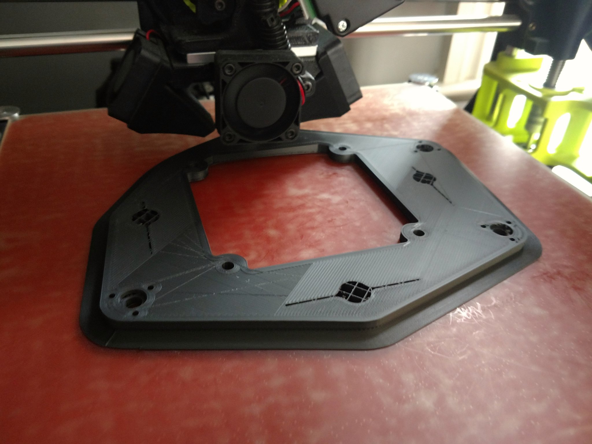
The first one should be done by tonight. In the meantime I've been looking at wiring. Lots of people out there recommend making up a new harness independent of the stock wiring to bypass the CANBUS and any other limitations of the stock harness. I'll likely be going this route so over the weekend while the parts print I'll pick up components and rig that up. With any luck I'll be rolling again in a few days!
The first one should be done by tonight. In the meantime I've been looking at wiring. Lots of people out there recommend making up a new harness independent of the stock wiring to bypass the CANBUS and any other limitations of the stock harness. I'll likely be going this route so over the weekend while the parts print I'll pick up components and rig that up. With any luck I'll be rolling again in a few days!
02-07-2019, 05:12 AM
#10
Super Moderator
Thread Starter
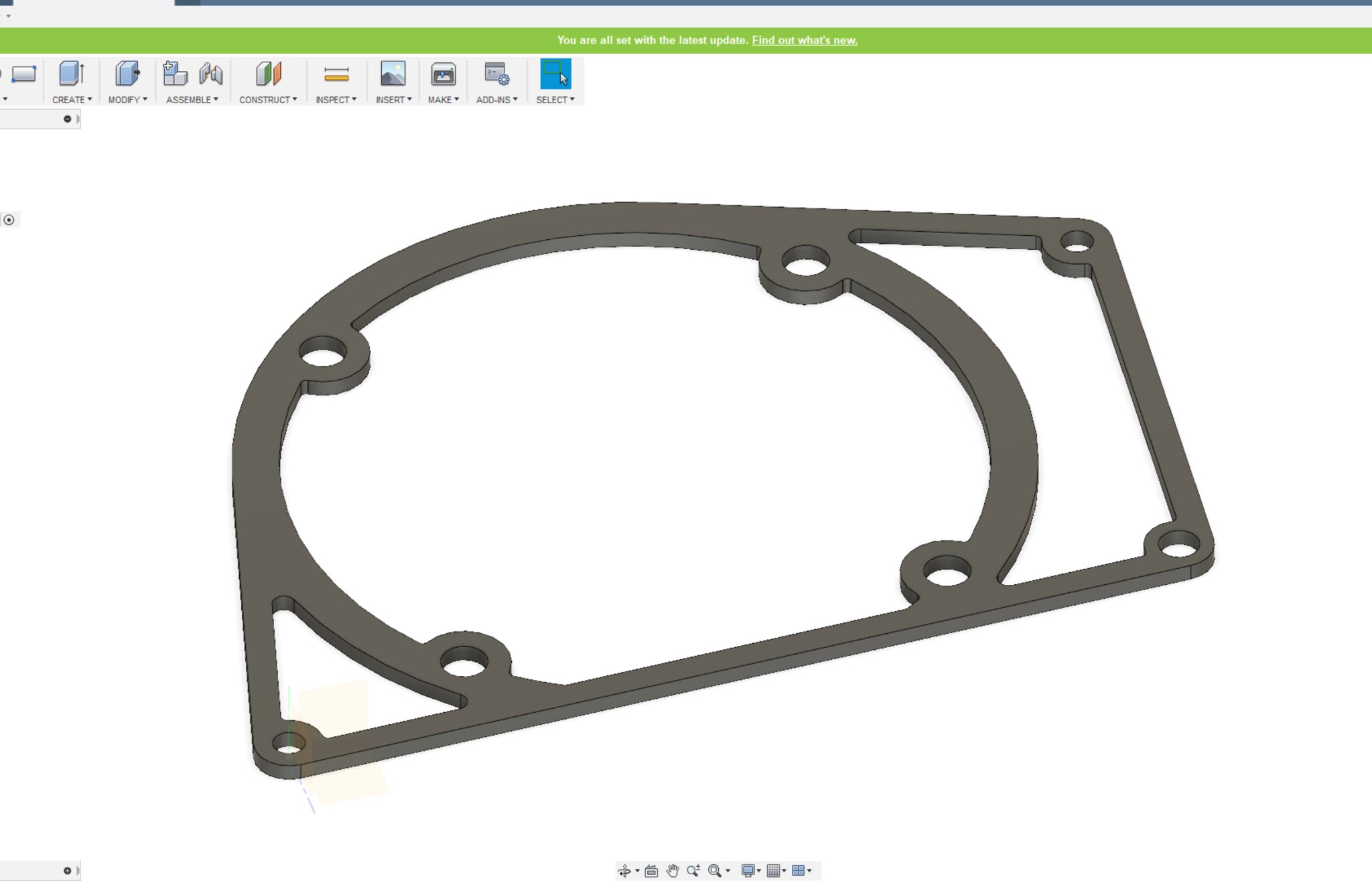
Progress! I spent a lot of time tuning the printer to make the parts as slick as possible. That means each (finished) piece takes 10 - 24 hours to print so there's been a lot of down time on the design. I ended up starting the mounting plate from scratch to reposition the holes and iron out some small issues. I'm probably going to do some minor modifications to that before finalizing it to increase stiffness. I worked out the adjustment solution and I'm happy with it. It utilizes the stock holes so I can go back to a stock setup (or any aftermarket setup) with no problems.
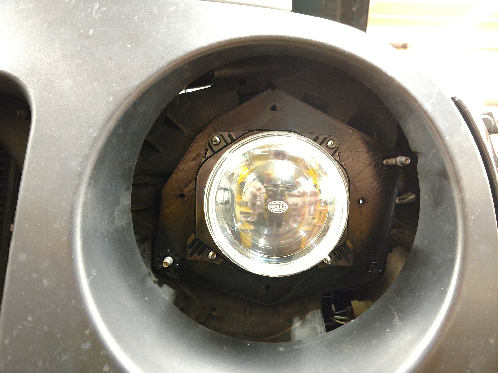
I ended up using a 3 part system. The first is the plate that holds the projector to the Jeep. This has standoffs to hold the next plate. See pic:
That plate serves as a second stiffener and a solid spot to mount the shroud. I figured I'd put all the structure into two components that stay put so I have freedom to make the shroud flimsy and disposable in case they break or if I want to swap them out for different looks. The 'fitting' shroud in place now is super simple with some holes carved out to cut down on material.
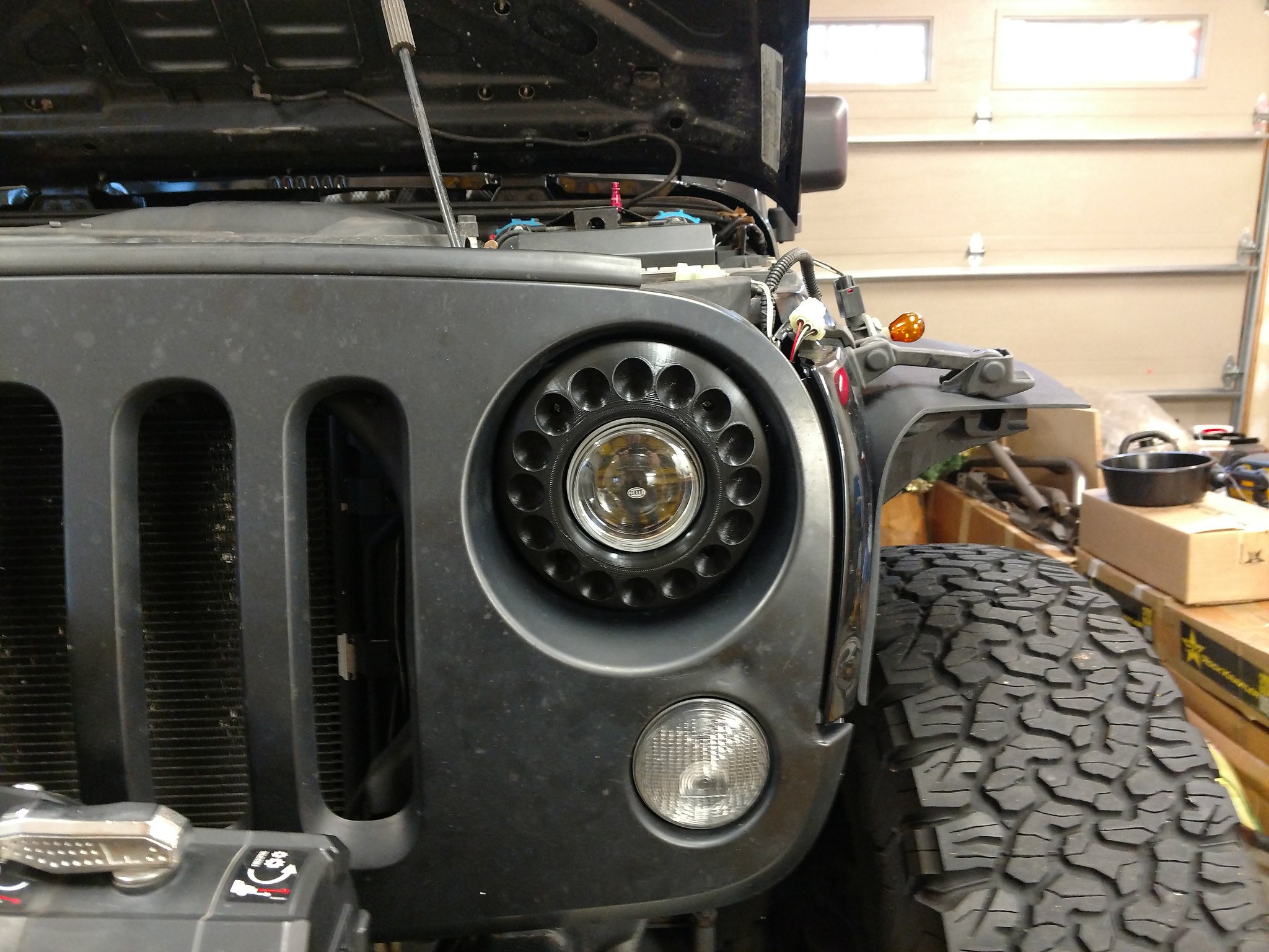
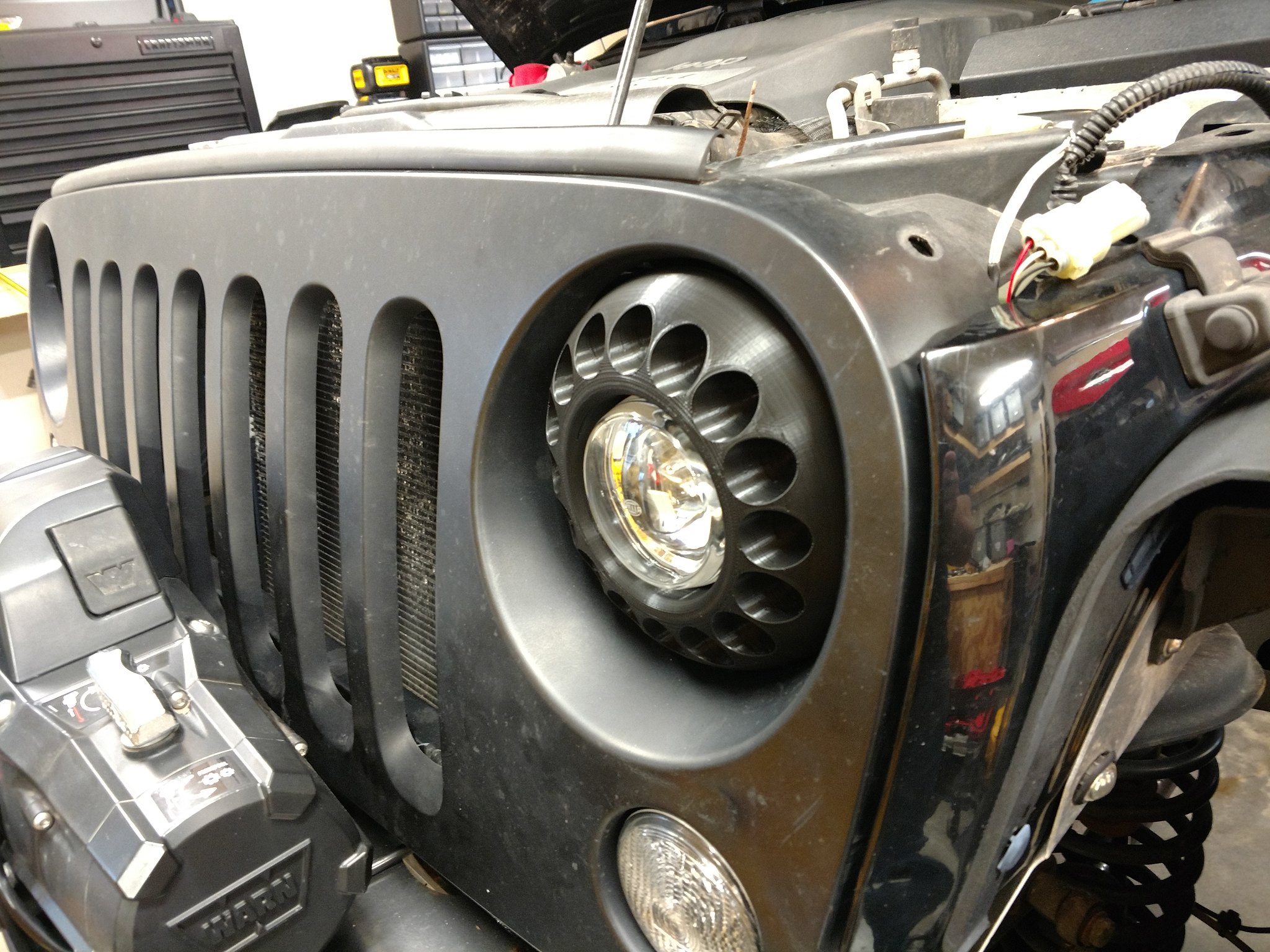
I think the fit is great. Tight clearances around the projector and inside the grill but with enough room to move for adjustment. I did forget to add the little recesses for adjustment access but that's exactly why I do these quick fit parts. Before I go any further with the printing, I want to get the headlight aimed. Backing everything down to the substructure definitely does not point the light straight ahead. I'll rig the projector to fire up right from the battery and get it aimed close to where it should go. Then I can check that everything sits at the right depth, etc. I have half a dozen ideas for shrouds so I'm going to start whipping some of those up, ten hours at a time.
I have some concerns about the wiring. Bypassing the stock wiring seems like it will leave me open to fault codes and headlight out dash warnings. I don't think I can hurt anything though so I'm going to start trying things and see if there are really any issues. I have some anti-flicker harnesses from the last set of LED lights which I suspect are just capacitor/diode/resistor combos. They don't want to open up and I haven't decided yet if I want to break them open or possibly use them in line with my wiring. I'll cross that bridge if initial attempts fail.
So far I'm pleased though. Looks like it's going to pan out nicely.
I ended up using a 3 part system. The first is the plate that holds the projector to the Jeep. This has standoffs to hold the next plate. See pic:
That plate serves as a second stiffener and a solid spot to mount the shroud. I figured I'd put all the structure into two components that stay put so I have freedom to make the shroud flimsy and disposable in case they break or if I want to swap them out for different looks. The 'fitting' shroud in place now is super simple with some holes carved out to cut down on material.
I think the fit is great. Tight clearances around the projector and inside the grill but with enough room to move for adjustment. I did forget to add the little recesses for adjustment access but that's exactly why I do these quick fit parts. Before I go any further with the printing, I want to get the headlight aimed. Backing everything down to the substructure definitely does not point the light straight ahead. I'll rig the projector to fire up right from the battery and get it aimed close to where it should go. Then I can check that everything sits at the right depth, etc. I have half a dozen ideas for shrouds so I'm going to start whipping some of those up, ten hours at a time.
I have some concerns about the wiring. Bypassing the stock wiring seems like it will leave me open to fault codes and headlight out dash warnings. I don't think I can hurt anything though so I'm going to start trying things and see if there are really any issues. I have some anti-flicker harnesses from the last set of LED lights which I suspect are just capacitor/diode/resistor combos. They don't want to open up and I haven't decided yet if I want to break them open or possibly use them in line with my wiring. I'll cross that bridge if initial attempts fail.
So far I'm pleased though. Looks like it's going to pan out nicely.