HID sealed projector retrofit


 02-07-2019, 01:13 PM
#12
Super Moderator

Thread Starter
I'm drawing them up in Fusion 360 and slicing them in Cura. It was (still is) a challenging learning curve but so, so worth it. I had been using Google Sketchup for years which is super intuitive, but extremely limited. It's so hard to start over but F360 makes a lot of sense to me now and I'm glad I took the time. There are other programs out there, notably Solidworks, that I'm interested in trying but I think I'm going to be happy with what I've got now for a while.
02-09-2019, 05:24 AM
#13
Super Moderator
With the TruckLites and even Axial LED headlights there are codes that show in the superchips about headlight draws lower than expected but I do not get any actual CEL or bulb out warnings on my 10 or 16. I'd venture to say you'd experience the same with your jeep. Another point of reference, at one point in time I had a 10" LED bar running off of one of my fog light harnesses- never had an issue there.
Kudos on the 3d print work. The toughest part (aside from the learning curve) is the patience for those things to print. I have access to one and got the 07-10 defrost redirection pieces printed up. They're due for a redesign but the work that goes into getting the small details ironed out is what slows me down. I'm using TinkerCAD/ AutoCAD but may have to look into the F360. Google sketchup didn't really suite my needs and what I felt I was looking for.
Kudos on the 3d print work. The toughest part (aside from the learning curve) is the patience for those things to print. I have access to one and got the 07-10 defrost redirection pieces printed up. They're due for a redesign but the work that goes into getting the small details ironed out is what slows me down. I'm using TinkerCAD/ AutoCAD but may have to look into the F360. Google sketchup didn't really suite my needs and what I felt I was looking for.
02-09-2019, 11:05 AM
#14
Super Moderator
Thread Starter
I've been working on the harness and so far no problems so I'm optimistic.
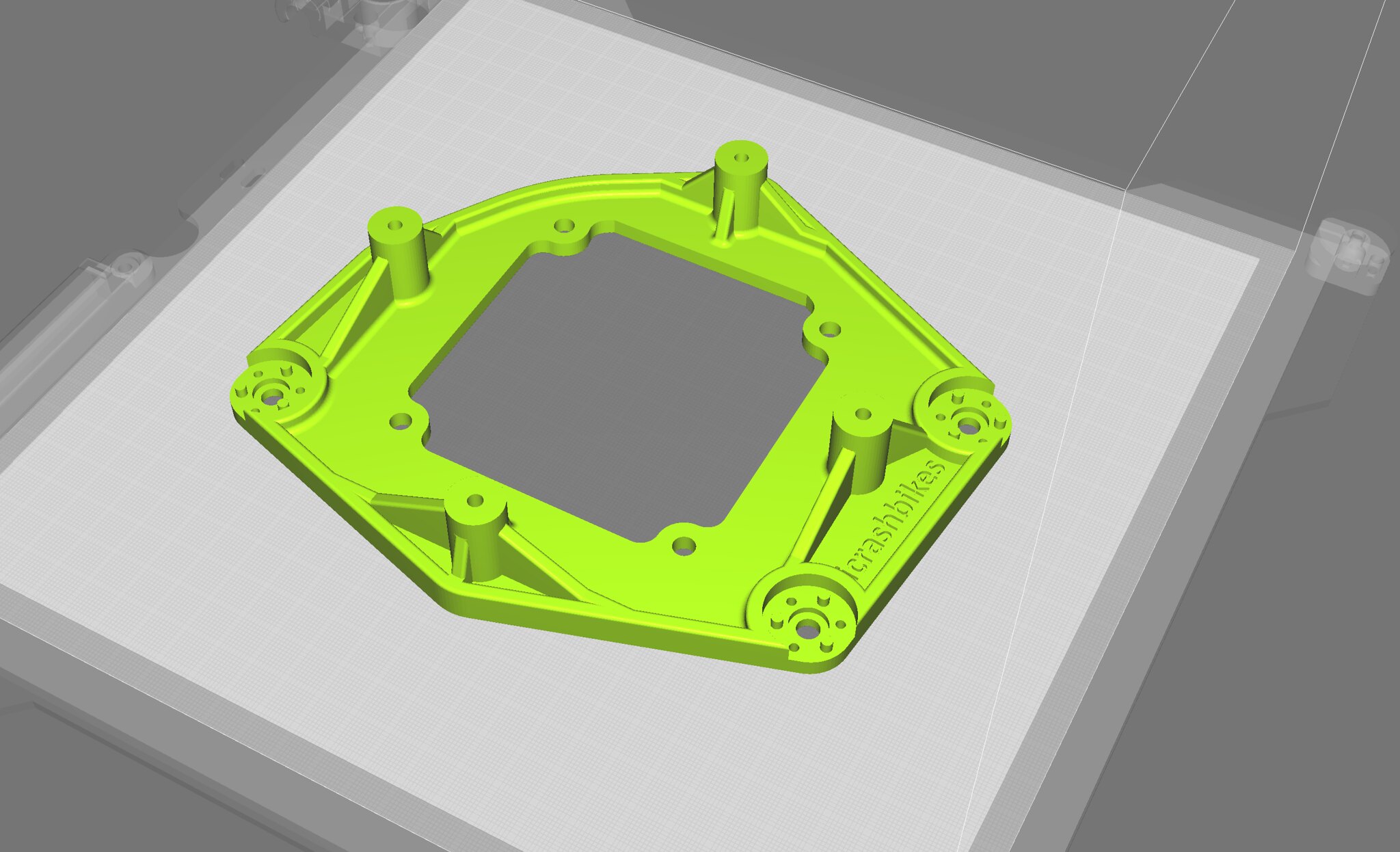
I'm currently on hour 4 of a 24 hour print. Doing the driver side mounting bracket in super high quality. I have to make the walls thick to accept the screw threads and I have infill at 40% for a little additional strength. There wasn't much flex at all in the current bracket, but I added a raised seam around the edge to add some stiffness. Here it is in Cura on the build plate:
On a more aggravating note, I'm planning for mounting the ballasts so I'm trying to find some space. I successfully modified the horn bracket (two bends in the vise) so that's clear. There seems to be plenty of room behind the headlight buckets down by the turn signals. I pulled one fender liner to get better access and NOTHING wanted to come out. I ended up slotting one of the stainless button head screws after it stripped out. I'm going to swing by jeep or advanced and pick up a few of those slip on nut thingers, mine are all in garbage shape. Just time right down the drain! I should actually go pick that stuff up now.
02-10-2019, 06:53 PM
#15
Super Moderator
Thread Starter
Painful day. I noticed at hour 21 that the back of the bracket was lifting and I had to abort. That happens sometimes with this material, it's challenging to print with. I haven't found a better finished material though so I'll try again. Given the empty printer, I took the opportunity to start fitting some other pieces for this project. I decided on a place to mount the relay and run the wiring harness. Naturally, rather than just screw the relay into the sheet metal somewhere, I found a nice spot and designed a bracket to put it exactly where I want it. It was a tough spot to measure so I started with a paper template and went on to go through NINE fit templates to get it right. That's more than usual. Then I started printing the finished bracket and the &^#*@!% thing curled on the print bed. I'm on take 3 of that print now after adjusting the settings and setting up a space heater to try to mitigate the temperature difference that causes the warping. It's looking good so far. I have the preliminary wiring done for testing which I may or may not do while that bracket prints.
Fit templates:

Relay & harness:

Actually I did figure out something cool today, each light will have 3 connectors. One for the ballast (low beam triggered switched power from the relay), one for the high beam (direct from stock high beam trigger), and one for "other". The other connector will be a 4 pin with options for the shrouds. One is turn signal, one is DRL (shuts off when the headlight comes on) and one is just auxiliary switched power for whatever. That last pin is a ground. This way I can design a new shroud with any or all of those features in LEDs and use a standard plug to make them work. Maybe it's just me and I'm a big dork but that sounds like fun. I didn't even have to work that hard for it, I had the signal and aux rigged up from the last set of LED headlights and I'm using a 5 pin relay which has the handy-dandy normally closed lead that translates directly to a DRL. I was really hoping to get more done this weekend but it was busy and this was a slow progress kinda day. Looks like work is going to suffer next week while I keep playing with this!
Fit templates:
Relay & harness:
Actually I did figure out something cool today, each light will have 3 connectors. One for the ballast (low beam triggered switched power from the relay), one for the high beam (direct from stock high beam trigger), and one for "other". The other connector will be a 4 pin with options for the shrouds. One is turn signal, one is DRL (shuts off when the headlight comes on) and one is just auxiliary switched power for whatever. That last pin is a ground. This way I can design a new shroud with any or all of those features in LEDs and use a standard plug to make them work. Maybe it's just me and I'm a big dork but that sounds like fun. I didn't even have to work that hard for it, I had the signal and aux rigged up from the last set of LED headlights and I'm using a 5 pin relay which has the handy-dandy normally closed lead that translates directly to a DRL. I was really hoping to get more done this weekend but it was busy and this was a slow progress kinda day. Looks like work is going to suffer next week while I keep playing with this!
02-11-2019, 12:44 PM
#16
Super Moderator
Thread Starter
I finished the silly relay bracket and got that mounted. I printed one for the enormous fuse holder too because really, why not. Then I test-wired everything up to check function.The relay runs fine using the stock headlight wire as a trigger. No flicker issues. The bi-xenon solenoid for the high beams works also but there's a funny issue that I hadn't considered. The stock headlights do the dance where the low beams shut off when you put the high beams on. That means that when I switch the high beams on it shuts off the low beam trigger to the relay and cuts power to the ballast. Since I have this capacitor and diode here that were unnecessary, I'm thinking I can use the diode to connect the high beams to the low beams such that when the high beams are switched on, the high beam wire will provide the 12V to the relay while preventing the low beam line from powering the high beams when they are off. I don't know if it works that way in real life, but this is why we have buddies who know about this kind of stuff. Then I figure I can use the capacitor to "smooth out" any transitional voltage drop during the low/high switch. If anyone knows more about electronics than I do, please chime in! Aside from that minor hangup, all is well.
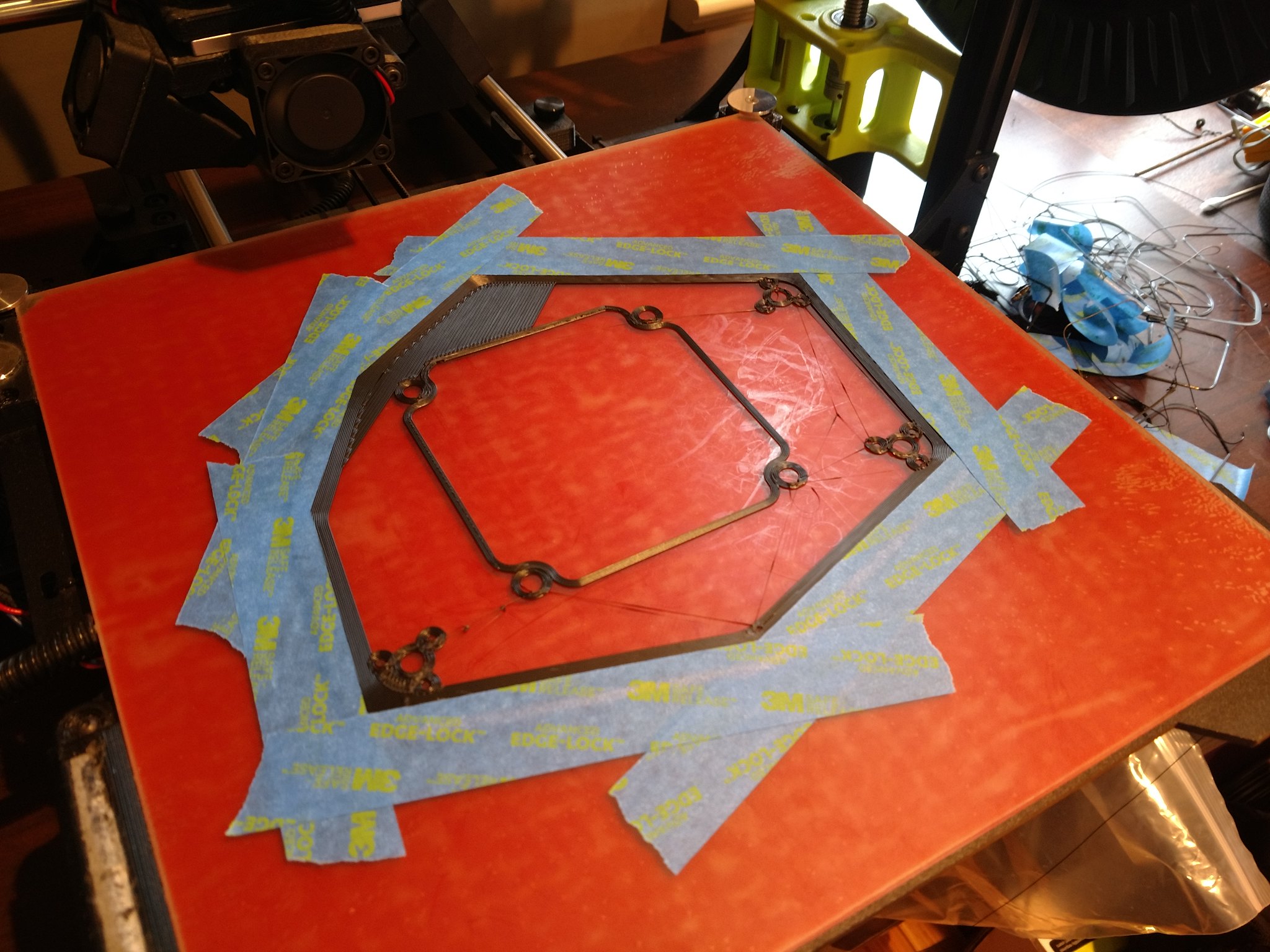
The big bracket is on its first layer as I'm typing. When I print with this material, I usually use a "brim" which is a number of lines laid down on the bed, attached to the part that help with adhesion by adding more surface area in contact with the build plate. It looks just like it sounds, like a hat brim around the base of the part. I had trouble even using a brim with warping on that relay bracket and I ended up taping the brim down to see if I could prevent lifting at the very edges. The point isn't so much to hold the part to the build plate, it's to keep the brim touching so it doesn't cool and start a sort of chain reaction of cooling and warping. It worked on the small part so I'm going to try it on the big one. In fact, I'm going to go do that now. I'll get a picture.
Ok I'm back. A quick pause, some tape and we're good to go. I hope.
The brim. Only 4 lines around are actually the edge of the part. The rest is sweet, sweet brim.
Taped:
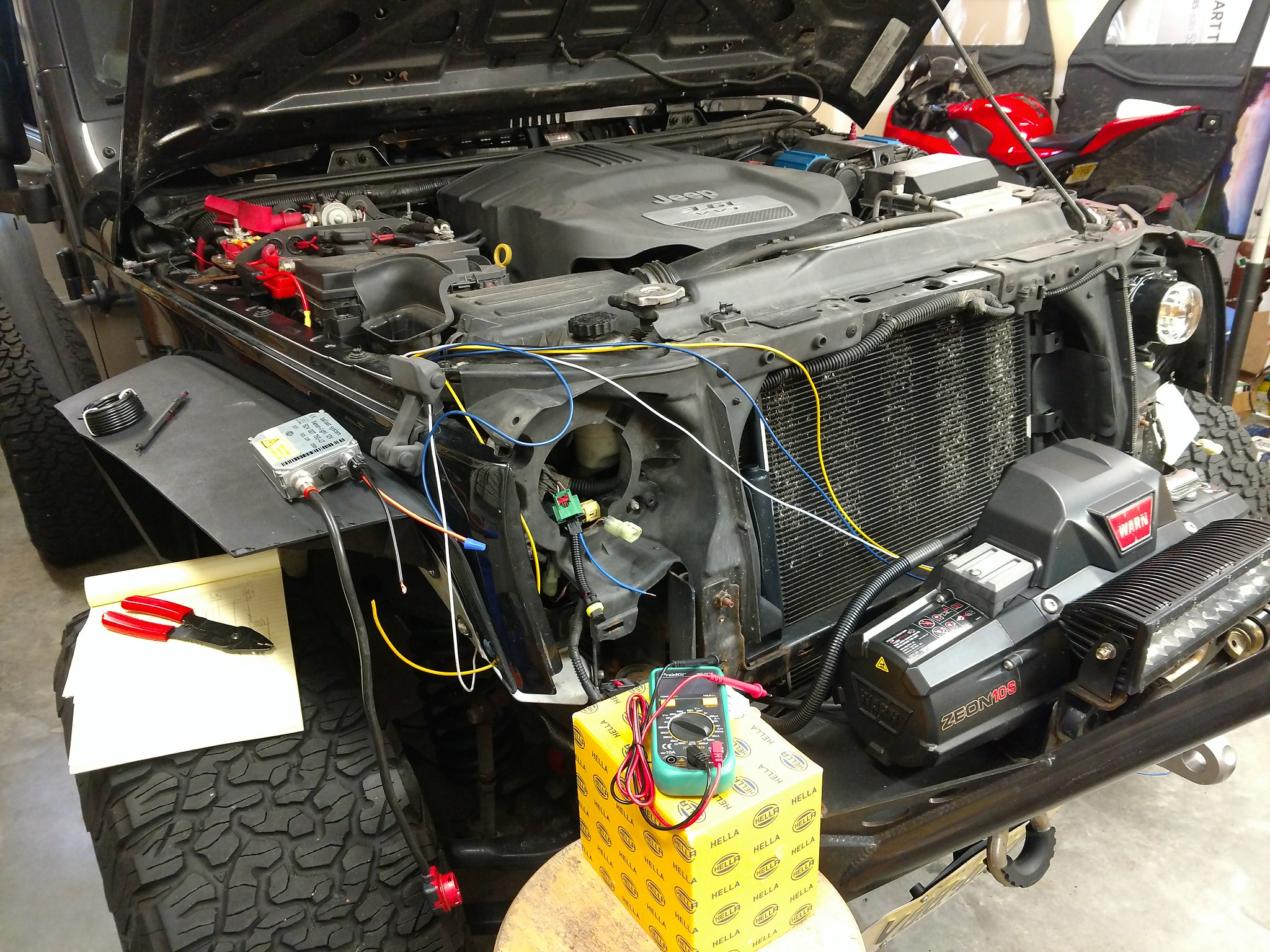
Relay in place:

And all the goofing around rigging things up with wire nuts to see what works:
The big bracket is on its first layer as I'm typing. When I print with this material, I usually use a "brim" which is a number of lines laid down on the bed, attached to the part that help with adhesion by adding more surface area in contact with the build plate. It looks just like it sounds, like a hat brim around the base of the part. I had trouble even using a brim with warping on that relay bracket and I ended up taping the brim down to see if I could prevent lifting at the very edges. The point isn't so much to hold the part to the build plate, it's to keep the brim touching so it doesn't cool and start a sort of chain reaction of cooling and warping. It worked on the small part so I'm going to try it on the big one. In fact, I'm going to go do that now. I'll get a picture.
Ok I'm back. A quick pause, some tape and we're good to go. I hope.
The brim. Only 4 lines around are actually the edge of the part. The rest is sweet, sweet brim.
Taped:
Relay in place:
And all the goofing around rigging things up with wire nuts to see what works:
02-12-2019, 05:13 AM
#17
Super Moderator
Thread Starter
The above print failed about 4 hours in. I put up some insulation from a nearby window (it's cold here), repositioned my space heater and wiped the build plate with alcohol. Some dirt definitely came off, I might add that to my regular routine. I set the same file to print again last night and we are over 12 hours into the 24 hour print and it's looking good. I think the clean print bed is probably the key. With any luck, this will be finished tonight and I'll start the passenger side bracket. Everything can be installed with the grill and winch in place, but I want to get the wiring harness finished and the ballasts mounted before closing it up. I'm researching the high beam fix still but if all the parts are finished before I have that ironed out, I'll just leave the high beams unplugged and put it all back together so I can have the frickin Jeep back. The high beam piece of the harness will unplug easily so it'll be simple to just pull one headlight, unplug some connectors and I can wire in what I have to on the bench. As long as the printer behaves, I can be reassembling in 36 hours.
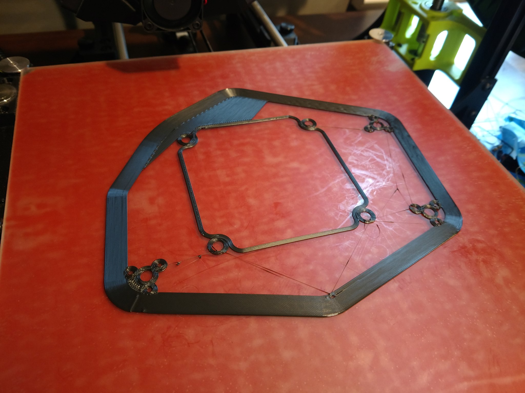
Here's the progress so far:
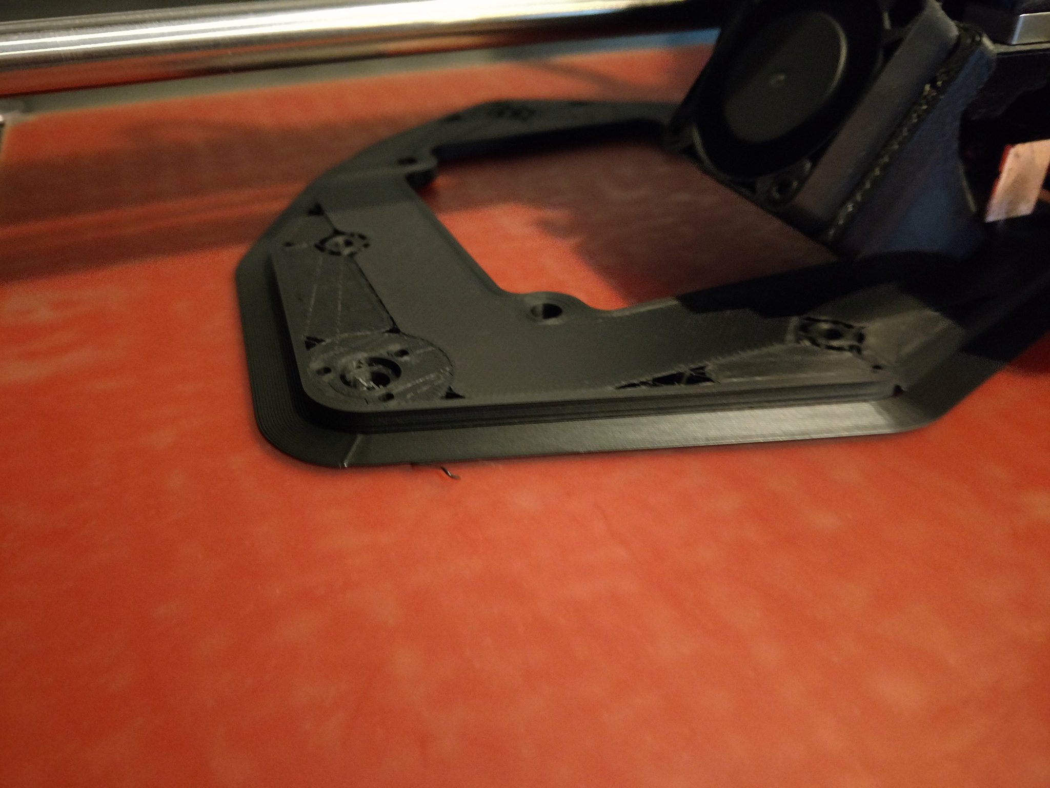
After looking at this picture I went back and took a closer look at the print. You can sort of see here at the back of the hole in the middle that it's lifted slightly off the bed. It's very minor and it's printing level now so I think I'm just going to let it ride. The bracket is still square, this will turn out as a slight depression on the back side. Next one I'll print with a brim on the inside as well as the outside to try to hold it down. What a pain!
Here's the progress so far:
After looking at this picture I went back and took a closer look at the print. You can sort of see here at the back of the hole in the middle that it's lifted slightly off the bed. It's very minor and it's printing level now so I think I'm just going to let it ride. The bracket is still square, this will turn out as a slight depression on the back side. Next one I'll print with a brim on the inside as well as the outside to try to hold it down. What a pain!
02-12-2019, 07:52 AM
#18
Super Moderator
Thread Starter
Ok! I had a solid sit down with someone who does electronics way better than me. We boiled it down to a 2 relay system that keeps all the features I'm planning. I'll need to order a time delay relay to prevent any voltage interruptions during the hi/lo switch, but other than that I'm good to go. For anyone interested in the solution:
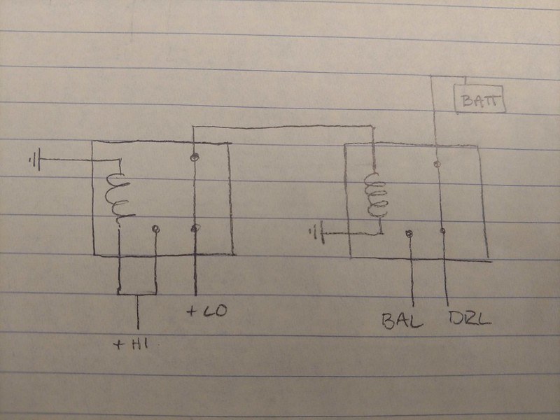
The right relay provides direct batter power to the projectors (BAL for ballast) and whatever DRL I come up with. That will be the time delay relay, which is kind of a bummer because I just made a bracket and wired up the standard relay in that spot. The left relay will handle the hi/lo beam switch. Since this isn't about powering a high beam bulb, it's about maintaining power to the projector, both lo and hi beam inputs result in a positive trigger on the main relay. The delay in the main relay will cover the time it takes that left relay to switch back and forth. The actual high beam solenoid will be activated by the high beam circuit elsewhere. I feel good about this! Now if I could get the parts to print flat!
Hey btw are my pictures too big? I'm over here on a big 4k monitor but the ones I post are probably gigantic on a regular 1080 screen. I can make them smaller if that would be better.
02-12-2019, 09:33 AM
#19
Super Moderator
Thread Starter
Aaaaand F. Sometime during the 20 minutes that I don't go look at the printer, the part came loose, slipped off the bed and madness ensued. The printer doesn't know when things go wrong so it just keeps going on its routine. Filament everywhere. This is my first major malfunction in 5 years of printing. So I went about cleaning up. Filament had melted all over the nozzle and hot end and the way I usually clean up this kind of mess is to warm up the nozzle to print temps to soften the filament and wipe it off with a mini wire brush. Apparently there are exposed wires around back that I managed to short with the steel bristles. Blew a fuse in the control box. That's not bad in itself, but these are mini fuses that I don't stock here. Like super mini. I found some on Amazon and they should be here tomorrow but I'm dead in the water till then. The relay will take longer to get here so I'm back in a holding pattern.
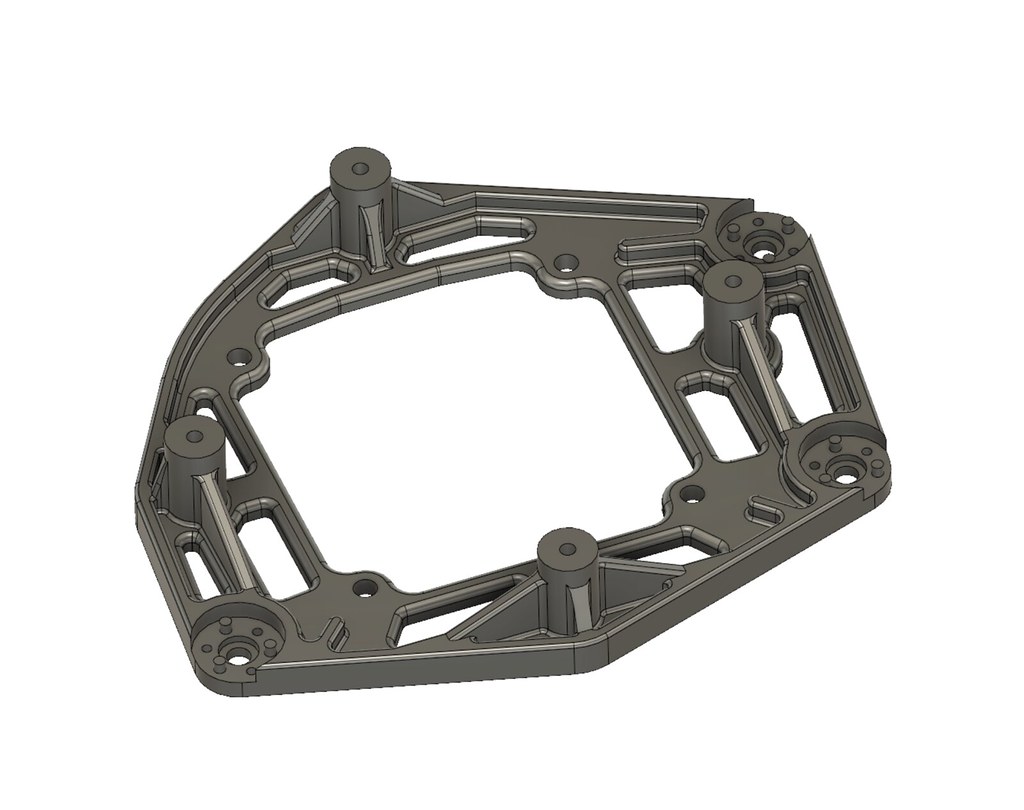
I'm considering punching some holes in the bracket designs. The last 20 hour failed print with the ribs was extremely stiff. Maybe I can use less material and create less of a temperature gradient across the part while printing to help mitigate the warping problem. I'll play with that in the down time. Maybe I'll do some work too. Bummer.
I'm considering punching some holes in the bracket designs. The last 20 hour failed print with the ribs was extremely stiff. Maybe I can use less material and create less of a temperature gradient across the part while printing to help mitigate the warping problem. I'll play with that in the down time. Maybe I'll do some work too. Bummer.
02-13-2019, 05:35 AM
#20
Super Moderator
Thread Starter
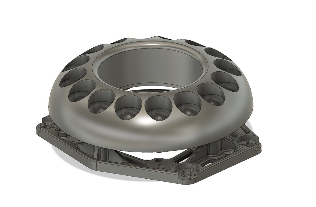
Fuses come today. Relay comes tomorrow. Till then enjoy some renders of the hopefully-more-printable mounting bracket and the three part assembly as it currently sits.