HID sealed projector retrofit
 02-14-2019, 04:59 PM
#21
Super Moderator

Thread Starter
Back in business! I'll spare you the story of getting the printer running again, but we're there. The new and improved bracket is on the way and looking great. With all the new cutouts print time is down to 18 hours, should be finished tomorrow morning. As long as that goes well I'll start the passenger side bracket which will finish friday night/saturday morning. I should have enough parts at that point to wire the whole setup and test it, but I'll have to wait for some sockets and pins before I can make everything finished and beautiful. Since no one offers an off-delay relay that's waterproof or a single or double relay waterproof housing, you guessed it, I'm gonna make one. I've done waterproof boxes before for RC electronics so it should go quickly. There should be enough room right where I mounted the single relay initially, and all the measuring work is done for that already. I should mount the ballasts too, that's the sort of thing that I'd just ignore till the very end and then whine and complain about how it's holding me up.
 02-16-2019, 04:21 AM
#22
Super Moderator
Thread Starter
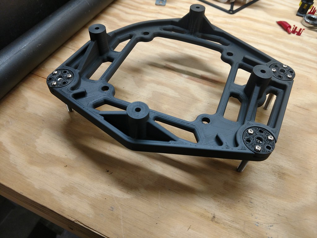
Success.
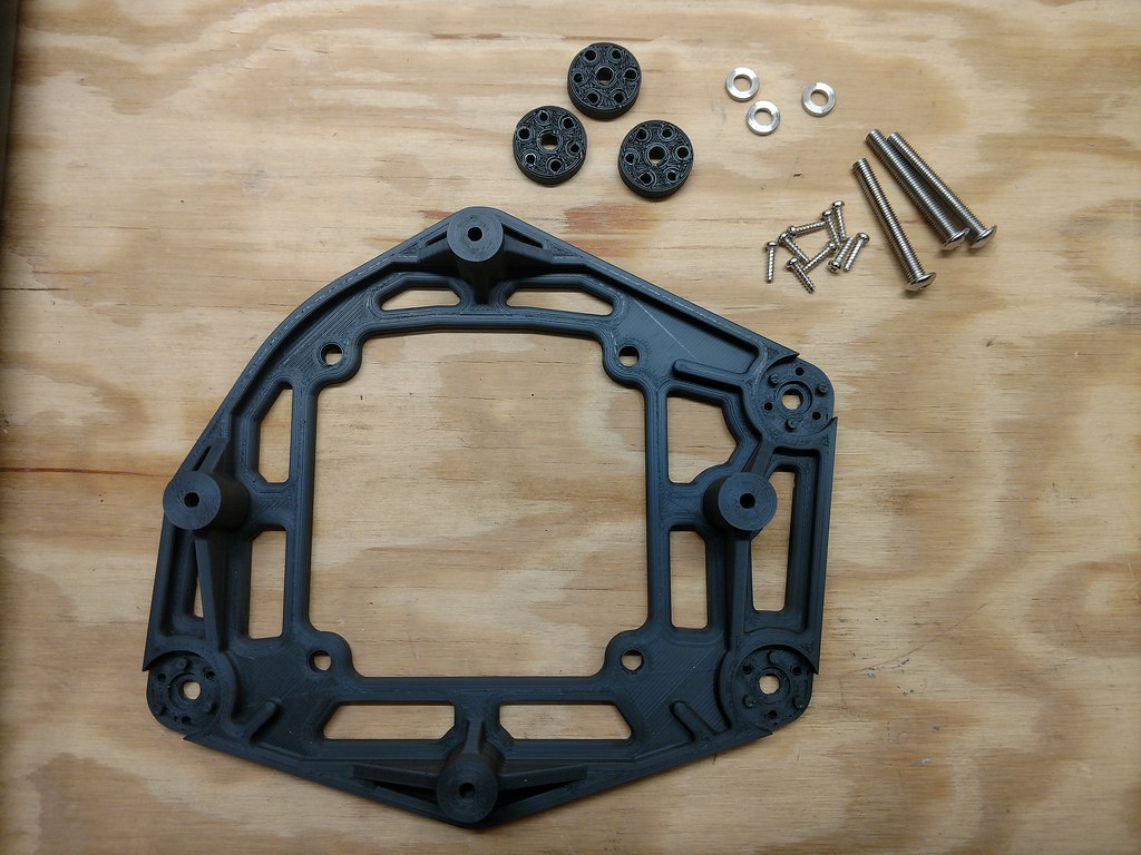
SS bushings pressed in, these are just to allow the adjustment screws to spin freely and to offer some additional strength:
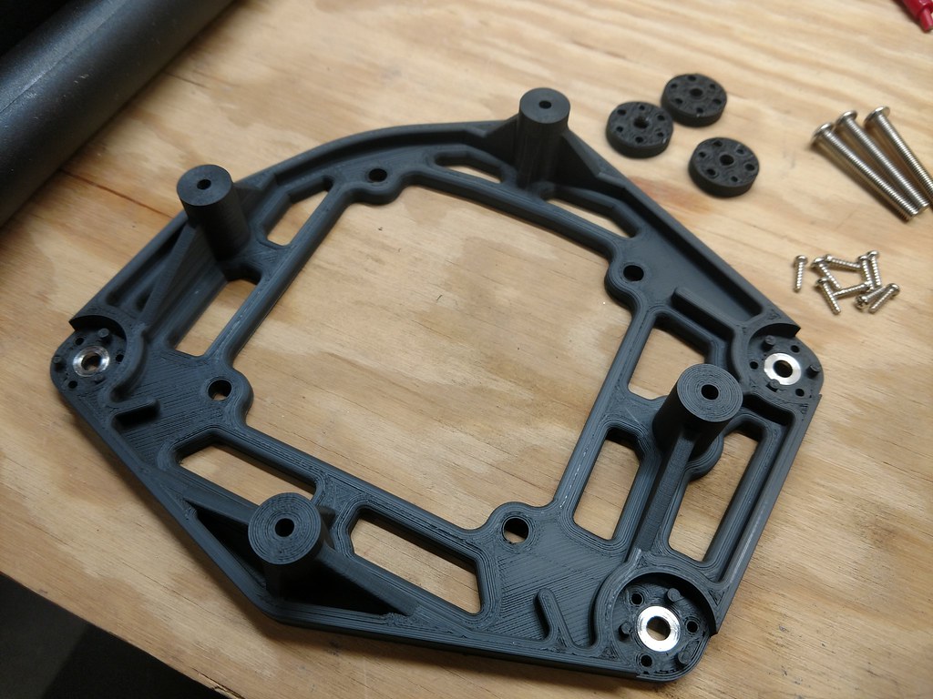
Adjustment screws and caps completes the adjuster assemblies. I may re-print these with the improved print settings:
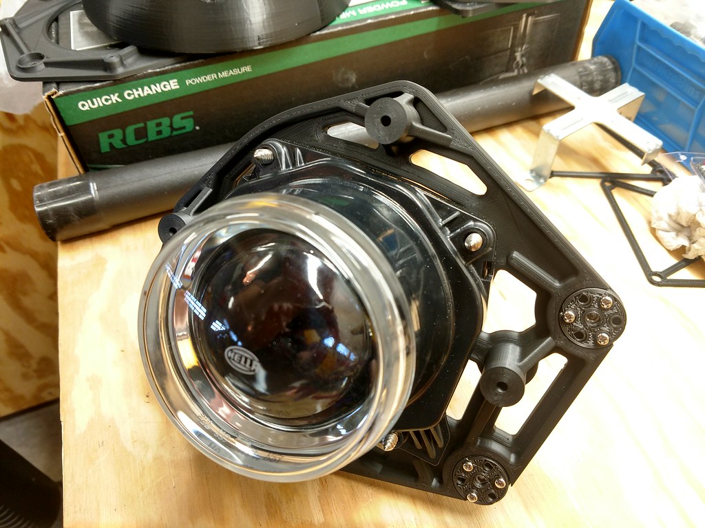
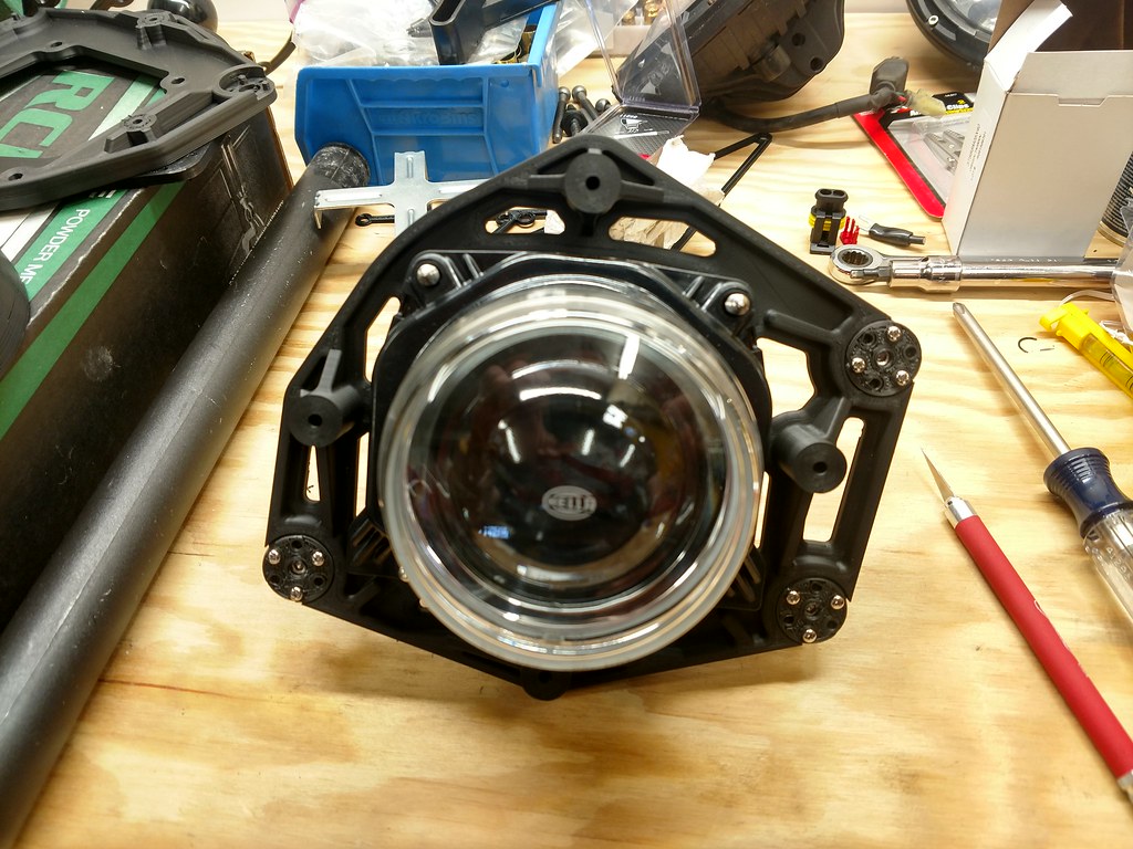
Projector mounted:
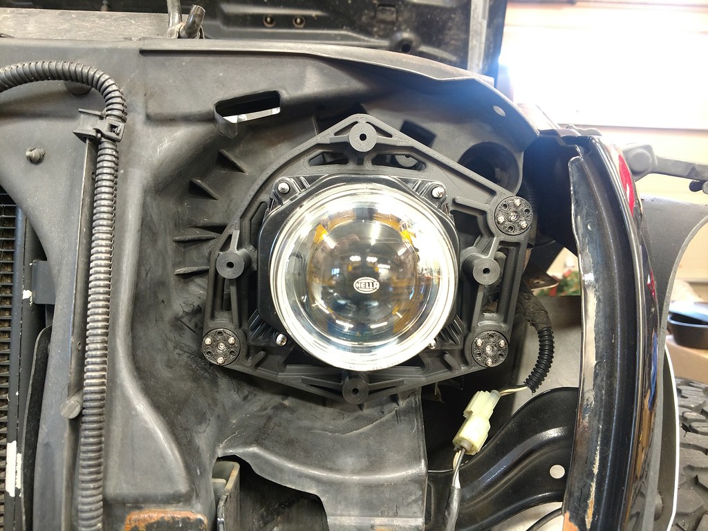
The whole jam mounted to the Jeep:
Unfortunately I ran out of time yesterday to get any farther than this, but I did start the passenger side bracket which should be finished this afternoon. Hopefully I'll get to test the relay switching today, make sure it will work. I did miss one important thing there, the relay I picked up is only rated at 10A. From everything I could find from the HID people, these Hella ballasts pull about 15A on startup. I have looked for a higher amperage delay/timer relay but without a lot of luck (for something reputable with a quick delivery time). I'll probably just use the 10A relay to switch a third relay that will handle the power delivery. It's more relays than I wanted but I can always change it later.
SS bushings pressed in, these are just to allow the adjustment screws to spin freely and to offer some additional strength:
Adjustment screws and caps completes the adjuster assemblies. I may re-print these with the improved print settings:
Projector mounted:
The whole jam mounted to the Jeep:
Unfortunately I ran out of time yesterday to get any farther than this, but I did start the passenger side bracket which should be finished this afternoon. Hopefully I'll get to test the relay switching today, make sure it will work. I did miss one important thing there, the relay I picked up is only rated at 10A. From everything I could find from the HID people, these Hella ballasts pull about 15A on startup. I have looked for a higher amperage delay/timer relay but without a lot of luck (for something reputable with a quick delivery time). I'll probably just use the 10A relay to switch a third relay that will handle the power delivery. It's more relays than I wanted but I can always change it later.
02-16-2019, 03:16 PM
#23
Super Moderator
Thread Starter
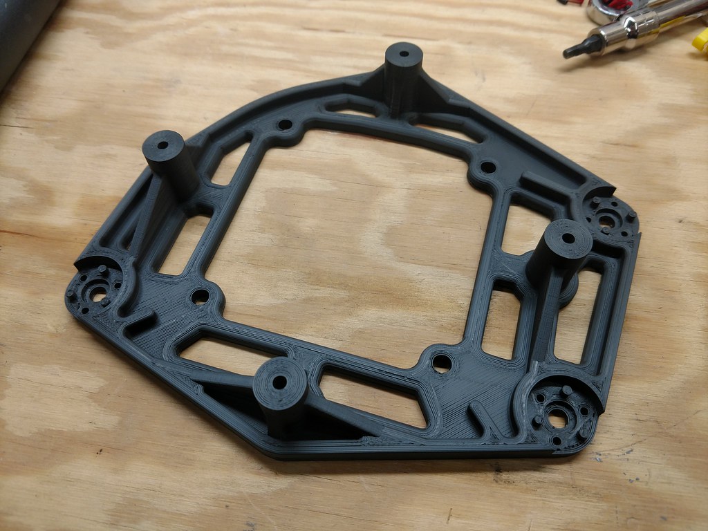
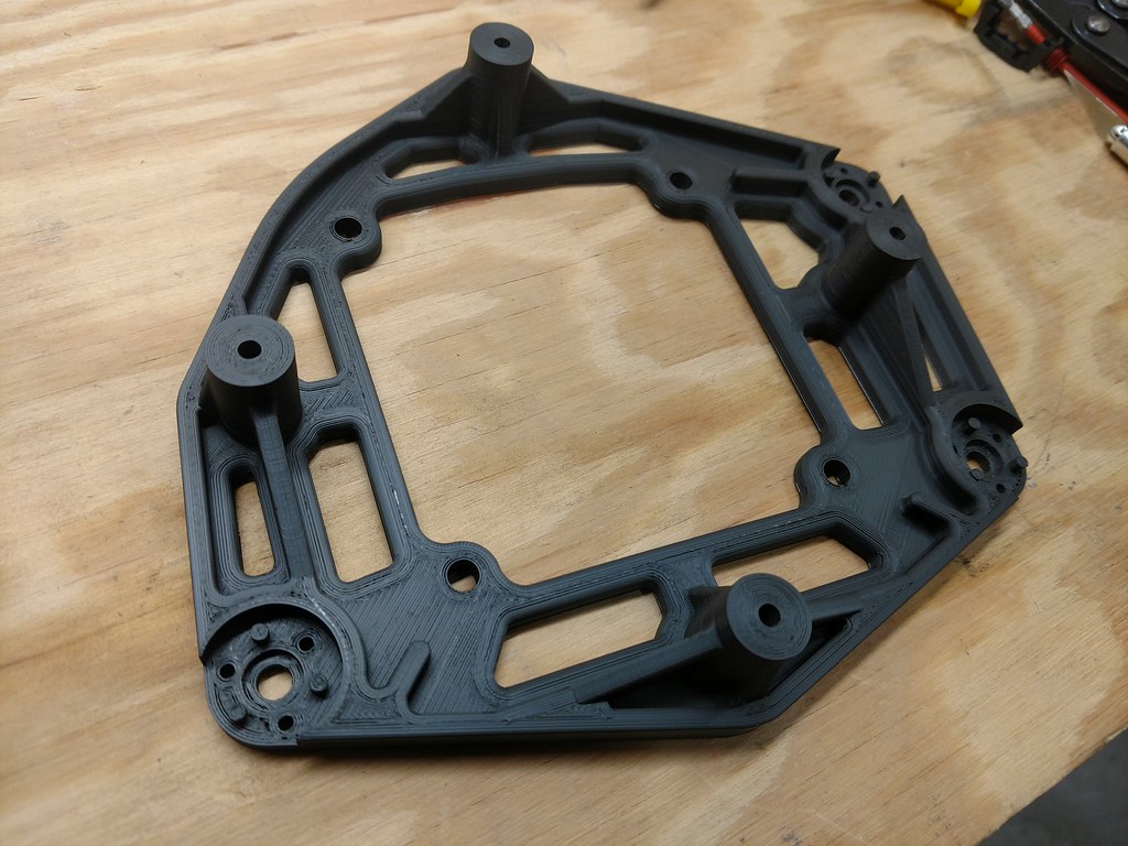
The thread view counter tells me people are reading this so I'm going to keep updating it!! I printed the three adjuster screw caps for the passenger headlight. I redesigned the shroud mount plate, the bracing on the previous one interferes with the projector housing since I shrunk the standoffs to pull the shroud back into the grill. Why is this three pieces you ask? I've been asking myself the same thing. What it boils down to is that I'm (by choice) limited to the flat build plate. I can print recesses and overhangs to a degree, but I've always built 3D printing-friendly geometry into my parts. If I did taller standoffs on the projector bracket and a flat-bottomed shroud, they would be held together with just the screws. The standoffs would butt up against the bottom of the shroud and I'd screw them together. With the loads the headlight shroud is likely to see, that's probably ok. But I don't like it. The shroud mount plate has recesses and fillets to mechanically secure the parts with a lot more support than just a butt joint and a screw. Yes, the shroud will sit on the plate flat to flat, but that's basically just the picture frame around the projector. I plan to have several shroud options including different lighting so it doesn't pay for me to build geometry in that might bite me later with interferences. That's my reasoning at least for over thinking the crap out of this. Here's the new shroud mounting plate, it's printing now, about 10 hours to go:

 02-20-2019, 03:41 PM
#25
Super Moderator
Thread Starter
Thanks! Been wiring today. Printing out shroud version 5. It's funny how when the design is function oriented it's so easy. When it's almost purely decorative I churn out some really crazy stuff. Hopefully the one finishing up now will be inoffensive enough to post pictures.
02-21-2019, 11:47 AM
#26
Super Moderator
Thread Starter
It works! I wound up with three relays but it actually works best this way to give me everything I want. I neglected to notice in the two-relay system that the DRLs would be hooked direct to battery with no shutoff. That would have been fun! I did hit an odd snag in that the system works correctly when I turn everything on but then it never turns off. I suspect the timer relay doesn't reset at the Jeep headlight's "off" voltage of 3.5v. I think I saw one with a higher threshold for turning off so I can keep going and swap them out when I get it. Here's the madness:
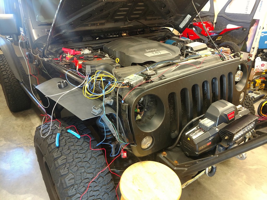
I wasn't about to wire anything up permanently without testing it first. There are 14 connections just to the relays. I borrowed switched power from the lighter in the dash which is why half the wires are running through the door. That circuit will power any LED running lights I decide to put in and it acts as the trigger for the ballast relay. Since there's no real load to it I'll just piggyback it off that line permanently. If I decide to add laser beams to the headlights, I'll just add another relay and use the DRL line as the trigger. But as it it functions as intended now. When the ignition comes on, the DRL comes on. When I switch the headlights on, the DRL shuts off. The high beams work like stock, though there is a slight delay. I didn't mess with them much so maybe that's something I can iron out. I also have connections ready for turn signals and I have some ideas for those. Actually it just occurred to me now that I have switched power already at the headlights from rigging up the previous LED units. That makes life easier.
Since it works it's time to start planning to box up all these relays and get them installed somewhere. I couldn't find a weatherproof timer relay so I picked up some waterproof relay sockets and I'll make a box to house the relays. That also lets me wire them up the cleanest, no splices in between relay terminals. I'm going to leave the ballast relay where it is since I made the mount already and it's close to the battery with the fuse. I'll find somewhere around the headlights for the box with the other two.
I've been putting a lot of effort into finding the right place for the ballasts. They are pretty big and space is tight. I'd like to mount them with the connectors down and as far away from water as possible, even though I should be able to submerge them without a problem. I think I have the spot, in the front corner of the fender. Some engine bays are just enormous with cavernous empty space, but not here! That's the least fun part of this project so far and I'm trying to just grit my teeth and get it done right before I ziptie them to something and forget them.
Shroud version 6 is printing now, done tomorrow. It's incredible how much the projectors and the grill make this look like an eyeball. I shoot for some neat design and when I put it on, all I see is some emotion. I've been through sad, dejected Jeep, sleepless, strung out Jeep, Arnold outside on Mars in Total Recall Jeep.. But with every design you learn something new. Again, this being purely decorative makes it more difficult. If I were adding DRLs and turn signals now, I'm sure the function would help dictate the form. If anyone wants to see the Jeep's range of emotion I'll put up a picture, if not I'm not going to volunteer it. Hopefully this one will be closer to cool and less like someone just dropped the Jeep's birthday cake. Oh my god I have to make white ones and go for disturbing realism. The possibilities are endless!!
02-22-2019, 04:55 AM
#27
Super Moderator
Thread Starter
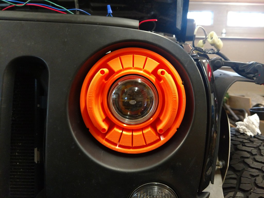
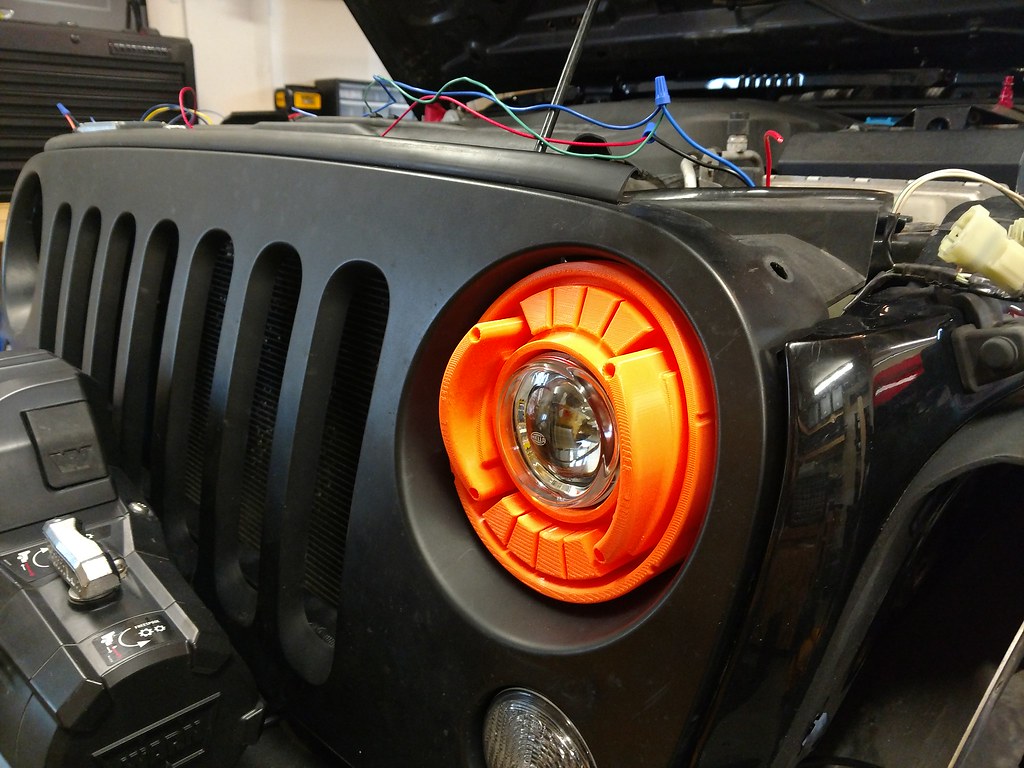
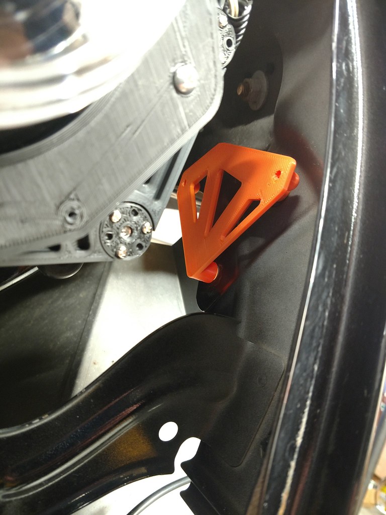
Finally finding what works in this headlight bucket. I'm doing some experimenting with lens guards, I figure if I can make anything I want I might as well aim for something useful. The shrouds look best when they mostly fill out the space between the grill recess and the projector. If it sticks out it looks bug-eyed and if it's recessed it looks sunken and beady. Take a look
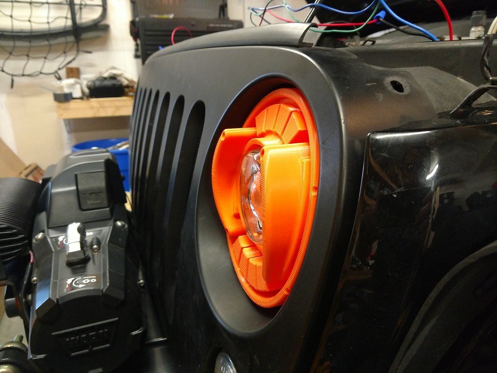
I might make the guards separate pieces so I can do more stuff with them and change them out. I also have a crazy idea for a full enclosure lens cover, something that would use a servo or solenoid to open and shut, covering the projector completely when the lights are off. Like pop up lights kinda.
Also no, orange is not the color I'm planning. I just happened to have some cheap orange PLA for prototyping. It's about 1/3 the cost of the material I'm planning on for the final part, though I expect the final part will be years and years from now after driving around with 400 mismatched prototypes in every color. I'm looking forward to that. I'm also tempted to do printed housings and LEDs in the turn signal holes to match the headlights. The possibilities are endless.
02-25-2019, 05:33 AM
#28
Super Moderator
Thread Starter
Ballast brackets are finished!

They use two holes in the fender for mounting and one bucket sorta thing that slides over the butt of one of the fender pop-in jobbies. The three together are very secure. It also lets me get rid of one of those speed nut clips which I dislike. It keeps the ballast tucked up in that corner of the fender away from as much crap as possible. Mostly I'm excited because that securing the ballasts was a headache that I wasn't looking forward to and it went off without a hitch.
The little waterproof house for the relays is on the printer now and I'm officially out of excuses, it's time to wire it up for real.
02-25-2019, 07:01 AM
#29
JK Jedi
Those last pictures of lens guards are interesting.....quite different. Can't wait to see what this finished product is going to look like.
02-28-2019, 01:02 PM
#30
Super Moderator
Thread Starter
The headlight wiring in this joint is very strange. I definitely don't claim to understand it. I've spent a lot of time trying to perfect and simplify a wiring solution and I'm still not 100% sure what will work best. Today I tried wiring in a stock headlamp and checking voltages coming from the low beam and high beam wires in the harness. Those values are different than what I get with an unplugged harness. They will likely also be different when I connect that harness to a relay instead of a bulb. I got a D in EE101 (don't worry, that wasn't my major) so this has all been a learning experience for me. Till now I've been very happy to work with positive 12V, switches, and a ground. Now I'm swimming in relays and diodes and capacitors. The good news here is that I whittled it down to a two relay system, I think that's pretty definite. Which is great, because I've been making parts to that effect. For your entertainment, here are the first bits rolling out for the waterproof dual relay housing:
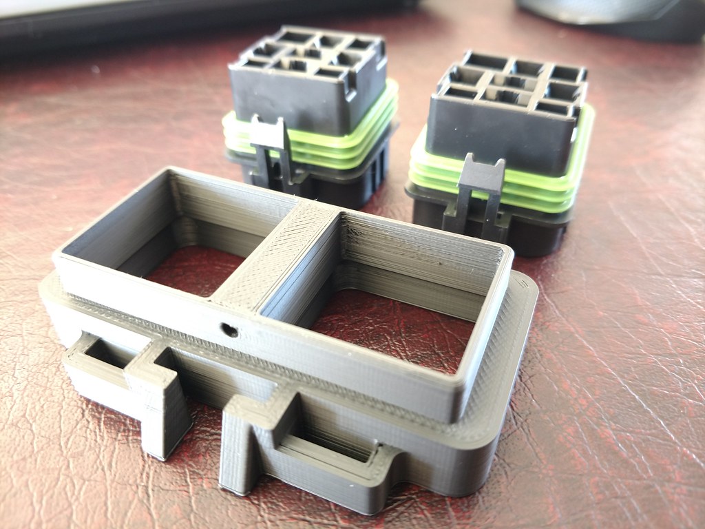
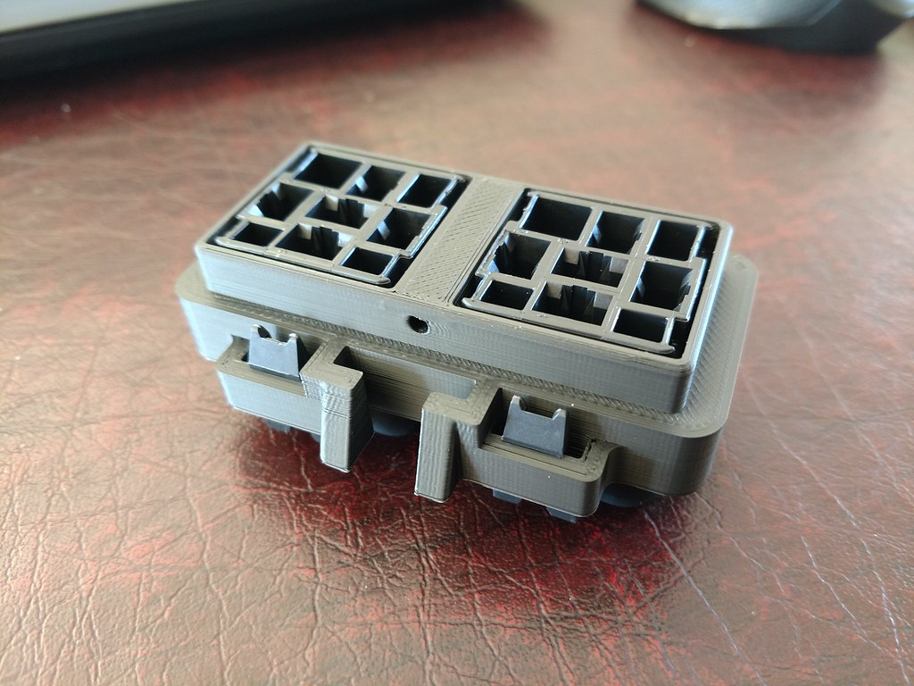
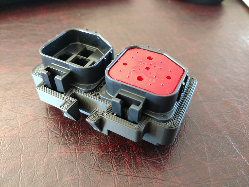
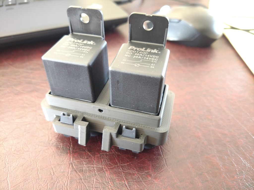
There is a cover that will go over the relays and screw in where that hole is. If I get the chance to go dig through the o-rings at the o-ring store, I'll add a recess for one. For now it's a snug fit and I'll just put a little bead of silicone to keep the water out. The whole assembly will sit on a bracket with a dovetail so any part can be swapped out at any time. The rest of the parts will be done tonight so hopefully I can find some quiet time over the weekend to find out what works and make the harness.