Relay Question and Fog Lights wiring Diagram layout
 04-22-2015, 06:02 AM
#1
JK Newbie
Thread Starter
I'm getting some "spaghetti syndrome" re-wiring my top HID lights and my new front fogs. I have a couple questions.
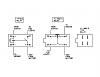
First, the relays that came with my HIDs were a YL-388-s type relay. Trying to find a wiring diagram for this has been a pain. It has the parallel pins and #'ed differently. First, is this layout correct?
Then, looking at this picture...
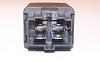
What is the position of the 30 pin? My assumption is that the "notch" portrayed on the diagram is notch for the latch and not the bottom notch. correct?
Then, this is my setup for the top 4 55w HID lights. Let me know if you see a problem using one switch for both my 40 amp relays:
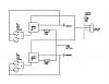
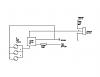
Then, this is my setup for my front 3 55w fog lights. Using the same 40amp relay and 30 amp fuse, does anyone see a problem with this? Typically you don't want to connect 3 lights to one relay but I believe that these 40amp ones could handle it.
Thanks in advanced for all your help!
First, the relays that came with my HIDs were a YL-388-s type relay. Trying to find a wiring diagram for this has been a pain. It has the parallel pins and #'ed differently. First, is this layout correct?
Then, looking at this picture...
What is the position of the 30 pin? My assumption is that the "notch" portrayed on the diagram is notch for the latch and not the bottom notch. correct?
Then, this is my setup for the top 4 55w HID lights. Let me know if you see a problem using one switch for both my 40 amp relays:
Then, this is my setup for my front 3 55w fog lights. Using the same 40amp relay and 30 amp fuse, does anyone see a problem with this? Typically you don't want to connect 3 lights to one relay but I believe that these 40amp ones could handle it.
Thanks in advanced for all your help!
 04-22-2015, 06:32 AM
#2
JK Junkie
I'm not familiar with that relay but the control circuit is connected via a coil in the relay. Use a multimeter to test continuity between the two control pins. That should be at or near zero resistance. Then you know you have the right ones. Assuming it is a normally open relay.
The only things I would do differently from you schematics is run the light grounds to the chassis. This will allow shorter wire runs and smaller gauge wiring. Adding pin numbers would be helpful as well.
The only things I would do differently from you schematics is run the light grounds to the chassis. This will allow shorter wire runs and smaller gauge wiring. Adding pin numbers would be helpful as well.
Last edited by 14Sport; 04-22-2015 at 06:36 AM.
04-22-2015, 06:53 AM
#3
JK Newbie
Thread Starter
I'm not familiar with that relay but the control circuit is connected via a coil in the relay. Use a multimeter to test continuity between the two control pins. That should be at or near zero resistance. Then you know you have the right ones. Assuming it is a normally open relay.
The only things I would do differently from you schematics is run the light grounds to the chassis. This will allow shorter wire runs and smaller gauge wiring. Adding pin numbers would be helpful as well.
The only things I would do differently from you schematics is run the light grounds to the chassis. This will allow shorter wire runs and smaller gauge wiring. Adding pin numbers would be helpful as well.
Regarding the diagrams, these relays already have a ground wire attached at the base of the relay harness connector for the lights. I already pre wired them to it. Just followed along the power wire inside my light bar to my relay in my engine compartment. The pin #s really depends on my prior question to make sure I have the right setup but good point.
Thanks!
04-22-2015, 07:06 AM
#4
JK Junkie
Not the control circuit. The pins should show continuity with the relay in your hand. Once you identify the control pins, you can apply 12 volts across them and then the load pins should show continuity.
The ground pin on a relay is for the control circuit. If you are going to run your light grounds to the same pin, make sure the ground wire from that pin to the battery or chassis can handle the load. I have never seen a relay wired like that, and I've seen hundreds.
The ground pin on a relay is for the control circuit. If you are going to run your light grounds to the same pin, make sure the ground wire from that pin to the battery or chassis can handle the load. I have never seen a relay wired like that, and I've seen hundreds.
Last edited by 14Sport; 04-22-2015 at 07:34 AM.
04-22-2015, 07:47 AM
#5
JK Newbie
Thread Starter
Not the control circuit. The pins should show continuity with the relay in your hand. Once you identify the control pins, you can apply 12 volts across them and then the load pins should show continuity.
The ground pin on a relay is for the control circuit. If you are going to run your light grounds to the same pin, make sure the ground wire from that pin to the battery or chassis can handle the load. I have never seen a relay wired like that, and I've seen hundreds.
The ground pin on a relay is for the control circuit. If you are going to run your light grounds to the same pin, make sure the ground wire from that pin to the battery or chassis can handle the load. I have never seen a relay wired like that, and I've seen hundreds.
04-22-2015, 07:57 AM
#6
JK Junkie
Really? Google 40 Amp Universal Wiring Harness. Most of these kits come like that.
Attachment 607622
Attachment 607622

Probably because I make my own harnesses.
04-23-2015, 09:28 AM
#7
JK Newbie
Thread Starter
FYI: For future reference for anyone else that comes across the YL-388-s type relays, the schematic above for the pin layout is correct. Just finished up my upper lights last night with this.
Trending Topics
11-27-2017, 03:44 PM
#8
JK Newbie

Join Date: Dec 2015
Posts: 4
Likes: 0
Received 0 Likes
on
0 Posts