Wiring Additional Back-Up Lights
 12-20-2010, 06:05 AM
#21
JK Enthusiast
Join Date: Dec 2008
Location: Northwest, Indiana
Posts: 268
Likes: 0
Received 0 Likes
on
0 Posts
The last time I was at my local auto store and said "I need a so and so", it took them an hour to find what I needed. No part number, no decent service.
I'll buy one online.
I'll buy one online.
 03-17-2013, 07:28 PM
#25
JK Junkie
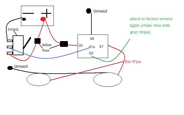
In order to wire your aux reverse lights to come on by using a dash mounted switch AND also be activated by shifting into reverse, follow the wiring diagram below. Note that you will need a relay with an 87A pin (available at napa). The factory reverse light wire you will need to tap is the white wire with gray stripe. Just remove the 4 screws that secure your tail light lens to acess the wires behind it. Locate the reverse light bulb and then find the white wire with gray stripe.
Here ya go...Excuse my shitty microsoft paint rendering
RELAY:
86: to ground
87: to aftermarket fog lights (white wire)
87A: to center terminal on switch
85: to white wire w/ gray stripe (factory reverse)
30: to battery with inline fuse
Here ya go...Excuse my shitty microsoft paint rendering
RELAY:
86: to ground
87: to aftermarket fog lights (white wire)
87A: to center terminal on switch
85: to white wire w/ gray stripe (factory reverse)
30: to battery with inline fuse
03-17-2013, 07:29 PM
#26
JK Junkie
03-19-2013, 06:03 AM
#28
JK Junkie
Here is a drawing that works.

Last edited by JK-Ford; 03-19-2013 at 06:10 AM.
03-19-2013, 07:48 AM
#29
JK Junkie
The 87A terminal indicates a "Normaly Open / Normaly Closed" relay. Terminal #30 is the "Common" pin. When the relay is OFF, power flows from terminal #30 to Terminal #87A. And when the relay is ON, power flows from Terminal #30 to Terminal #87. So, in this drawing, the switch does nothing.
Here is a drawing that works.
12-29-2017, 05:14 AM
#30
JK Newbie

Join Date: Dec 2017
Location: Roxbury
Posts: 2
Likes: 0
Received 0 Likes
on
0 Posts
Don't realy understand what you did. But I'll try to explain anyway.
1) 12 volt + from battery - to - #30 on relay.
2) #87 on relay - to -lights ( ground lights ).
3) From reverse light - to - either 85 or 86 on the relay. ( doesen't matter witch one ).
4) 85 / 86 on relay ( witch ever one is left )- to - ground.
1) 12 volt + from battery - to - #30 on relay.
2) #87 on relay - to -lights ( ground lights ).
3) From reverse light - to - either 85 or 86 on the relay. ( doesen't matter witch one ).
4) 85 / 86 on relay ( witch ever one is left )- to - ground.
I am new to this forum, found your posts when searching for a way to connect my aux rear lights to a switch and my reverse lights. In the diagrams there is a reference to a relay with pole 87A, but in this post you omit 87A.
I am using a Apollointech SPOD (SPST) switch and have connected everything as you have written above, but I cannot get it to work. Is pole 87a needed as the diagram suggests or does your written method work? I do not see the switch connection.
Any help would be appriciated.
GJS