Trouble Connecting Relay Box to sPod Switch Panel
 04-03-2015, 10:57 PM
#1
JK Enthusiast
Thread Starter
Join Date: Sep 2014
Location: Sun Prairie, WI
Posts: 293
Likes: 0
Received 0 Likes
on
0 Posts
Hello,
I have an AngryOffroad Relay Box, similar to the source box of the spod, but it has 4 relays and a bigger look. I'm trying to connect the wires from the relay box to the OTRATTW switches on the spod overhead switch panel. My OTRATTW switches are independent/dependent. Top lights up when turned on, bottom lights up when dashboard lights are on. If anyone is able to help me out, that would be great! Will post pictures if I have someone willing to try and help
I have an AngryOffroad Relay Box, similar to the source box of the spod, but it has 4 relays and a bigger look. I'm trying to connect the wires from the relay box to the OTRATTW switches on the spod overhead switch panel. My OTRATTW switches are independent/dependent. Top lights up when turned on, bottom lights up when dashboard lights are on. If anyone is able to help me out, that would be great! Will post pictures if I have someone willing to try and help
 04-04-2015, 02:26 AM
#2
JK Junkie
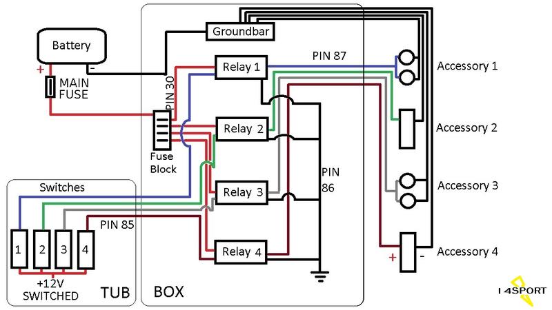
This is the overall look at the wiring. For your particular switches, I would need to see a pin diagram for your switches. You probably have pins for power and ground to the lower LED, A pin for the 12v source, a pin for the feed to the relay, and a ground pin for the upper LED. If you could post the pin out from their web site it would be helpful.
Independent lowers means you can wire the bottom LEDs to come on and dim with the dash lights if you want as I did to the sPod setup in this link.
https://www.jk-forum.com/forums/jk-e...lights-311176/
Independent lowers means you can wire the bottom LEDs to come on and dim with the dash lights if you want as I did to the sPod setup in this link.
https://www.jk-forum.com/forums/jk-e...lights-311176/
Last edited by 14Sport; 04-04-2015 at 03:23 AM.
04-05-2015, 03:58 AM
#3
JK Junkie
From your description, it sounds like this is the pinout for your switches.

This should make it easy for you. Let me know if you have any additional questions.
This should make it easy for you. Let me know if you have any additional questions.
04-05-2015, 05:05 AM
#4
JK Jedi Master


I could have used that day before yesterday when I was rewiring my sPOD controller so the panel light on-off switch was a function on-off switch (disaabling all sPOD functions unless on) and the panel lights were controlled through the dash lights. LOL.
04-05-2015, 05:09 AM
#5
JK Junkie
Haha...what did you do run the feed wire for pin 2 through the little button on the panel?
Looking at that I think I had to run only 1 wire from the dash light circuit because my pin 7 must be jumped to pin 8 from sPod.
Looking at that I think I had to run only 1 wire from the dash light circuit because my pin 7 must be jumped to pin 8 from sPod.
04-06-2015, 03:26 AM
#6
JK Jedi Master
No. I had the oil pressure gauge on the dash lights. Left the switch indicia lights as wired by sPOD through the switch because I had Contura II toggles. Too much bright light up there, even on dimmer. But when I replaced toggles with Contura XIVs, that problem was gone. So needed to move wire off switch to wire on O.P. gauge. But I'd rewired switch to also turn all sPOD functions off. Still wanted to retain that feature, so had to figure out how to rewire my rewiring job.
Last edited by Mark Doiron; 04-06-2015 at 03:28 AM.
04-07-2015, 06:32 PM
#7
JK Enthusiast
Thread Starter
Join Date: Sep 2014
Location: Sun Prairie, WI
Posts: 293
Likes: 0
Received 0 Likes
on
0 Posts
Thanks for all the replies, I haven't gotten time to get on the forum until today. Here are some pictures of what I have so we'll have somewhere to start.
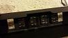
Picture above are my switches. The view is from the back and top to bottom. I believe I notice the pin layout already posted here, so we can refer to that when needed.
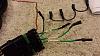
Picture above is what attaches to the pins on the back of the switches. The 3 green wires (should be 4, but one was pulled off) are the wires that come from the relays that I will show you next. The black/gray wire is a ground. The red is a constant power.
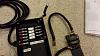
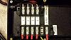
Picture are above are of the relay box itself. The box has a ground and power wire that attaches to the battery. Inside the box are four relays and fuses. From the relays, they attach to the screws above which are labeled for each relay. The '4-Rev Ground' was an extra attachment made by the previous owner.
With pictures posted, are you able to tell me how everything should be wired? Pin attachments, and from the light pods to the box itself. I am not too smart with electronics build, so I need help. I have attempted ways and tested, but no luck. Thanks for the help in advance.
Picture above are my switches. The view is from the back and top to bottom. I believe I notice the pin layout already posted here, so we can refer to that when needed.
Picture above is what attaches to the pins on the back of the switches. The 3 green wires (should be 4, but one was pulled off) are the wires that come from the relays that I will show you next. The black/gray wire is a ground. The red is a constant power.
Picture are above are of the relay box itself. The box has a ground and power wire that attaches to the battery. Inside the box are four relays and fuses. From the relays, they attach to the screws above which are labeled for each relay. The '4-Rev Ground' was an extra attachment made by the previous owner.
With pictures posted, are you able to tell me how everything should be wired? Pin attachments, and from the light pods to the box itself. I am not too smart with electronics build, so I need help. I have attempted ways and tested, but no luck. Thanks for the help in advance.
Trending Topics
04-07-2015, 11:01 PM
#8
JK Jedi Master
Is this WeatherPack connector ...

... the other end of the cable that is running out of the left side of this fuse/relay panel?

IOW, is that WeatherPack connector already wired up to the fuse/relay panel?
BTW, since we're on WeatherPacks: It takes a special crimping tool to properly attach the wire that's been pulled out of the connector. And it takes a special tool to remove the old pin that's likely still stuck in the connector ...
Spectro Wire and Cable: Weather Pack Crimping Tool
There are cheaper versions--I'll let you research that. Call Spectro and they can work with you on that.
Spectro Wire and Cable: Terminal Remover
And you'll need a replacement pin. And order several because it's very easy to munge those things when crimping them ...
Scroll part way down the page. And you'll also want the seal if it's been lost, also on that page ...
Spectro Wire and Cable: Weather Pak Connectors
And there are two companies that make those connectors, and they are not completely compatible. Ensure you get the right components. I think the pins and tools are completely compatible, but I know that the connector shells themselves are not. So it may be moot for you.
Also, back on that second picture: Is that device that appears to be a circuit breaker hard-wired to the fuse/relay box where the picture cuts it off at the bottom center? IOW, is that your primary power into the fuse/relay box?
... the other end of the cable that is running out of the left side of this fuse/relay panel?
IOW, is that WeatherPack connector already wired up to the fuse/relay panel?
BTW, since we're on WeatherPacks: It takes a special crimping tool to properly attach the wire that's been pulled out of the connector. And it takes a special tool to remove the old pin that's likely still stuck in the connector ...
Spectro Wire and Cable: Weather Pack Crimping Tool
There are cheaper versions--I'll let you research that. Call Spectro and they can work with you on that.
Spectro Wire and Cable: Terminal Remover
And you'll need a replacement pin. And order several because it's very easy to munge those things when crimping them ...
Scroll part way down the page. And you'll also want the seal if it's been lost, also on that page ...
Spectro Wire and Cable: Weather Pak Connectors
And there are two companies that make those connectors, and they are not completely compatible. Ensure you get the right components. I think the pins and tools are completely compatible, but I know that the connector shells themselves are not. So it may be moot for you.
Also, back on that second picture: Is that device that appears to be a circuit breaker hard-wired to the fuse/relay box where the picture cuts it off at the bottom center? IOW, is that your primary power into the fuse/relay box?
Last edited by Mark Doiron; 04-07-2015 at 11:05 PM.
04-08-2015, 01:59 AM
#9
JK Junkie
Sure looks like a weatherpack connector. If the wire you pulled out still has the pin on it then it is possible the pin just wasn't seated and you should be able to just reinsert it until it locks. Curious that there are 4 relays and 5 jumpers for ground. If it originally jumped pin 7 to 8 I would expect eight jumpers. And I would expect 4 jumpers for pin 2 of the power wire. And four jumpers for the pin 6 dash lights.
So first verify that that is the correct pinout for your switches. If so, then you should be able to:
1. Jump all the pins 7 and 8 together from the ground (black/gray) off the connector. So you will need 8 total connectors on the jumper.
2. Jump all the 2 pins together from the power (red) off the connector. (4 total connectors).
3. Run the relay (green) wires from the connector individually to pin 3 of each relay. The order you do this in will determine which switch triggers which relay/accessory.
4. Jump all the pin 6s together and feed from the dash light circuit. (4 total connectors).
Last edited by 14Sport; 04-08-2015 at 02:18 AM.
04-08-2015, 06:13 AM
#10
JK Enthusiast
Thread Starter
Join Date: Sep 2014
Location: Sun Prairie, WI
Posts: 293
Likes: 0
Received 0 Likes
on
0 Posts
Mark : I am not totally sure what the connector exactly is, but I Google the weatherpack connector and seemed to definitely look like it.
The connector and the other end on the box is not currently attached because I will have to feed it through the firewall. I will be connecting them using butt connectors for ease.
The connector is broken since the wire was pulled out. I have already ordered a new one to remake the connection. Lesson learned, don't pull out wires crimped inside.
The main power is that cable, the foot long on the right. It attaches to the battery itself.