PUMBAA - A project by Wildschwein
 10-12-2015, 10:58 AM
#1
JK Enthusiast
Thread Starter
Join Date: May 2013
Location: Utah
Posts: 264
Likes: 0
Received 0 Likes
on
0 Posts
I now begin my build thread. This first post will serve as a table of contents so that you'll be able to find what you're looking for. I'll attempt to keep it updated and in the proper order. Special thanks to the guys at sPod, BAS Off-road, Genesis, Metalcloak, and e-autogrills for having excellent customer service and helping me with any issue that came up. I'd also like to thank 14sport for the help with the sPod. If I left anyone out just let me know and I'll make sure you receive your props!
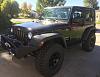
2013 Jeep "JK" Wrangler, 2-door, Engine: 3.6 Pentastar, Color: "Rugged Brown"
o 3" BDS suspension lift w/ adjustable LCA's and adjustable track bar
o 17" Mickey Thompson Classic III alloy wheels 5.5 lug pattern, 4.5" backpacking
o Atturo Trail Blade MT tires, 35 x 12.5 r17.
o Genesis Dual-Battery kit with g-screen monitoring system
o sPOD with safety switch on locker switches
o ARB Twin compressor w/ 2.5 gal Viair tank located on front cross member behind the front bumper (requires vacuum pump relocation)
o e-Autogrills "New England" front and rear bumper w/ tire carrier, as well as rocker guards.
o Uniden Bearcat CB with firestick flush mount antenna
o Rigid Industries JK Grille Insert for e-series light bar
o Bulldog 20" Bone Double-row LED light bar with combo flood pattern
o Bulldog 2" Spike Light Bar (flood) on the windshield hinges
o Bulldog 6" in the back
o Uniden Bearcat CB with firestick flush mount antenna
o Smittybilt X2O 12k winch with bluetooth wireless controller and synthetic line
o Trektop NX for that fastback look
o Bestop Element tube doors with pockets, enclosures, uppers
I think that's it for now. I'll try to keep this first post updated with links as I go.
Enjoy the rest of the thread!
Last edited by Wildschwein; 10-31-2015 at 07:41 PM.
 10-12-2015, 11:02 AM
#2
JK Enthusiast
Thread Starter
Join Date: May 2013
Location: Utah
Posts: 264
Likes: 0
Received 0 Likes
on
0 Posts
I did not take many pictures with the suspension lift because the instructions provided by BDS were excellent. I do have this before and after picture of my fender heights. Bear in mind that the rest of my mods all went on first which weighed Pumbaa down significantly in the front, which now rests a little lower than the rear. Otherwise, I did achieve about 2.5 inches of lift from the project.
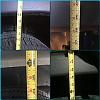
The install went very smooth with the only trouble being a rusted drag link tie rod end which ended up getting replaced anyway. I used a pickle fork to separate it and inevitably jacked up the grease boot.
The install went very smooth with the only trouble being a rusted drag link tie rod end which ended up getting replaced anyway. I used a pickle fork to separate it and inevitably jacked up the grease boot.
10-12-2015, 11:24 AM
#3
JK Enthusiast
Thread Starter
Join Date: May 2013
Location: Utah
Posts: 264
Likes: 0
Received 0 Likes
on
0 Posts
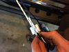
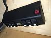
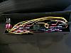
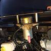
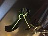
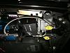
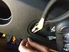
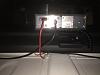
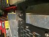
Again, the instructions from Genesis were excellent and made the install totally easy. The most difficult part was fishing the cables through the firewall to install the g-screen into the sPod. I've attached a few photos here to show that technique. I used a spring loaded 4 claw gripper tool that I bought at auto zone about 20 years ago. I was able to push it right through the firewall port and alongside the dash, then I pulled a small piece of cord through and used that to pull the cables for the sPod and the g-screen through. I was able to fit both cables and my CB radio power cables through the hole. Also, you can see I used a little double stick tape to locate the g-screen controller into the header while routing the cables. This was the ONLY place I could find to hide that thing. It did not want to fit anywhere else.
I'm not sure why so many of my images are getting flipped upside down when I upload them, but I'm not going to go in and edit every image on my computer. Sorry guys, but you'll have to rotate the images yourself if you need to reference them.
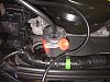
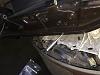
I'm not sure why so many of my images are getting flipped upside down when I upload them, but I'm not going to go in and edit every image on my computer. Sorry guys, but you'll have to rotate the images yourself if you need to reference them.
Last edited by Wildschwein; 10-12-2015 at 11:32 AM.
10-12-2015, 11:43 AM
#4
JK Enthusiast
Thread Starter
Join Date: May 2013
Location: Utah
Posts: 264
Likes: 0
Received 0 Likes
on
0 Posts
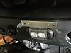
So for this post, you also check out 14Sport's links on all the sPod hacks. Very informative and pretty much where I got most of my information, but I'll show you how I did it anyway...
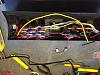
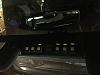
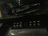
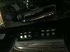
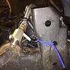
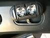
The idea was to wire in a STDP switch into the sPod that would render my last two switches, intended of the lockers, locked out unless both switches were thrown. That way I couldn't get a nosy passenger activating my lockers as we roll down the highway. Perhaps it's unnecessary, but I wanted to be sure and it was a fun project.
All the connections are soldered together and then wrapped in heat shrink. I basically interrupted the daisy chain along both the hot wire chain and the Positive LED power chains. That's why I need a double pole switch with a single throw. I wanted the LED indicator lights off when the switches weren't active. When the safety switch is unlocked, the LED's on the locker rockers light up and I know I can switch those on at will.
You'll also notice that I had to change out the bracket for the sPod source under the hood. That was ordered from Metalcloak and serves to suspend my vacuum pump underneath the sPod. The reason for this will be apparent in a subsequent post when I show my OBA install. The vacuum pump was removed and the bracket cut off to create space for the Viair tank on the cross member. So stay tuned for that!
all of my images are upside down here as well. Sorry about that guys, but it's just too much trouble to edit every shot before uploading... :(
10-12-2015, 11:46 AM
#5
JK Enthusiast
Thread Starter
Join Date: May 2013
Location: Utah
Posts: 264
Likes: 0
Received 0 Likes
on
0 Posts
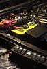
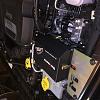
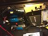
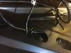
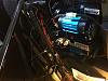
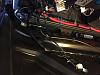
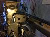
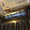
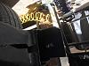
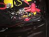
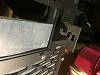
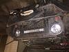
I'll start with the compressor. I mounted the ARB twin in the engine compartment using the M.O.R.E. mount, both of which I ordered from BAS Off-road for significantly less than the competition, plus they offer a military discount. So, big thanks to them and kudos for being a veteran run company.
Now, you'll remember when I installed the sPod that I suspended the vacuum pump beneath the power source module. The M.O.R.E. mount is compatible with the sPod, but not with the Metalcloak bracket for the pump relocation. It was a relatively easy fix to make them compatible. I loosely assembled everything together and then marked the compressor bracket where it would need to be cut. Fortunately it is a large bracket and with the sPod, you won't be using the excess material for mounting the locker solenoids anyway. Once I had it marked I was able to pull both brackets and overlap them again, this time tracing the contour of the vacuum pump onto the compressor bracket. A little work with the cutting wheel and a round file and my compressor bracket was compatible.
Be careful when installing the M.O.R.E. mount. The instructions are great, but what they don't tell you is that if you drill your holes from the top down you may very put your hold right next to one of the vertical ribs that create the structure for that plastic shelf you're drilling on to. If you do this, your bolt is going to be very difficult to place. I ended up having to flatten one side of my washer and even still I couldn't get a socket onto it, so I had to turn it ⅛ of a turn at a time with an open end wrench, flipping it each time. It was a PITA, so be careful not to make this mistake.
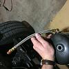
Following the mounting, I installed my air hoses. I discarded the nipple provided by ARB and instead installed all brass fittings form Lowes in �" NPT. I used two Viair leader hoses, one 18" male to male, and then a 36" male to male with a check valve going to the tank. I used thread sealant instead of teflon tape and I did so fairly liberally. After that I ran my wires. Since I'd already stuffed all the Genesis and sPod harnesses into the space behind the firewall wiring harness, I elected to run the ARB stuff along the underside of the hood. I also stuffed the wires for the lockers to eventually be installed inside the hood for now.
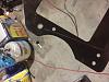
Now, you'll remember when I installed the sPod that I suspended the vacuum pump beneath the power source module. The M.O.R.E. mount is compatible with the sPod, but not with the Metalcloak bracket for the pump relocation. It was a relatively easy fix to make them compatible. I loosely assembled everything together and then marked the compressor bracket where it would need to be cut. Fortunately it is a large bracket and with the sPod, you won't be using the excess material for mounting the locker solenoids anyway. Once I had it marked I was able to pull both brackets and overlap them again, this time tracing the contour of the vacuum pump onto the compressor bracket. A little work with the cutting wheel and a round file and my compressor bracket was compatible.
Be careful when installing the M.O.R.E. mount. The instructions are great, but what they don't tell you is that if you drill your holes from the top down you may very put your hold right next to one of the vertical ribs that create the structure for that plastic shelf you're drilling on to. If you do this, your bolt is going to be very difficult to place. I ended up having to flatten one side of my washer and even still I couldn't get a socket onto it, so I had to turn it ⅛ of a turn at a time with an open end wrench, flipping it each time. It was a PITA, so be careful not to make this mistake.
Following the mounting, I installed my air hoses. I discarded the nipple provided by ARB and instead installed all brass fittings form Lowes in �" NPT. I used two Viair leader hoses, one 18" male to male, and then a 36" male to male with a check valve going to the tank. I used thread sealant instead of teflon tape and I did so fairly liberally. After that I ran my wires. Since I'd already stuffed all the Genesis and sPod harnesses into the space behind the firewall wiring harness, I elected to run the ARB stuff along the underside of the hood. I also stuffed the wires for the lockers to eventually be installed inside the hood for now.
Last edited by Wildschwein; 10-12-2015 at 08:47 PM.
10-12-2015, 08:50 PM
#6
JK Enthusiast
Thread Starter
Join Date: May 2013
Location: Utah
Posts: 264
Likes: 0
Received 0 Likes
on
0 Posts
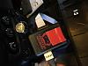
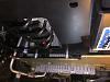
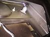
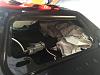
Here are the rest of the pictures from the compressor install. Also, it would appear there is one of my dog, who apparently needs to sit in my seat anytime I'm working on Pumbaa.
Again, the orientation of my pictures is entirely unreliable...
Again, the orientation of my pictures is entirely unreliable...
Last edited by Wildschwein; 10-12-2015 at 08:52 PM.
10-15-2015, 03:49 AM
#7
JK Enthusiast
Thread Starter
Join Date: May 2013
Location: Utah
Posts: 264
Likes: 0
Received 0 Likes
on
0 Posts
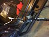
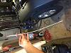
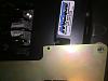
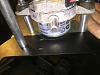
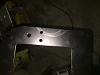
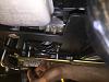
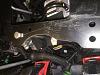
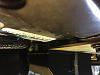
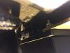
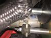
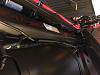
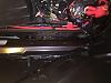
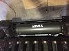
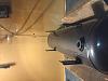
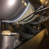
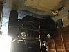
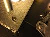
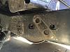
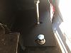
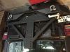
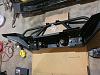
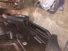
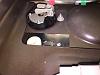
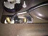
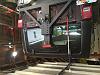
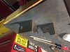
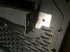
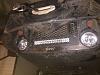
After reading tons of posts and recommendations for mounting a tank in the cargo area, behind the exhaust, in place of the evap canister, and even just running tankless, I decided to put mine up front behind the bumper. The problem is that there is little room here for a tank of this size. The solution, relocate the vacuum pump up to the engine compartment. There were several threads on relocating the vacuum pump, though I elected a product relocation with the Metalcloak bracket. This bracket remounts your sPod from its original mount to a new bracket designed to suspend the vacuum pump beneath in inside the engine compartment. Then I removed the original vacuum pump bracket with a reciprocating saw and used an angle grinder to clean up the edges.
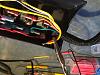
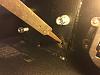
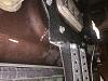
Once the vacuum pump was out of the way I was clear to mount my air tank. I'm not sure how satisfied I am with my mounting technique, so I'm open to criticism and suggestion. I chose to use two 5" hose clamps linked together in four locations securing the tank to the front cross member. I had considered bolting through the cross member and onto the tank legs, but could not find the perfect size bushings for that process. I did elect to leave my tank's legs attached incase I decided to re-mount this way if I happened across the right materials.
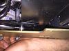
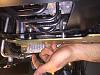
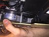
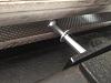
In order to fit the tank to the cross member and keep it low enough not to interfere with the installation of my e-autogrilles front bumper, I needed to remove the foot from the tank so it would sit flush to it's perch.
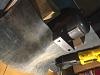
I buffered the tank with some rubber matting that I had, making sure to put more layers on the passenger side than the driver. This should serve to help condensation work its way to the drain. Speaking of the drain, make sure you install your drain hose prior to the tank as you will not be able to reach it once installed. I used a 10" steel braided hose I picked up at lower with a simple ball valve on the end and I installed a d-ring to clip it up out of the way when not in use. I used a three for leader hose to access my air for now and simply zip-tied it up inside my bumper and out of the way. I also fashioned a plug using a male quick connect and plug to put inside the port to protect it from dirt.
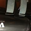
Once the vacuum pump was out of the way I was clear to mount my air tank. I'm not sure how satisfied I am with my mounting technique, so I'm open to criticism and suggestion. I chose to use two 5" hose clamps linked together in four locations securing the tank to the front cross member. I had considered bolting through the cross member and onto the tank legs, but could not find the perfect size bushings for that process. I did elect to leave my tank's legs attached incase I decided to re-mount this way if I happened across the right materials.
In order to fit the tank to the cross member and keep it low enough not to interfere with the installation of my e-autogrilles front bumper, I needed to remove the foot from the tank so it would sit flush to it's perch.
I buffered the tank with some rubber matting that I had, making sure to put more layers on the passenger side than the driver. This should serve to help condensation work its way to the drain. Speaking of the drain, make sure you install your drain hose prior to the tank as you will not be able to reach it once installed. I used a 10" steel braided hose I picked up at lower with a simple ball valve on the end and I installed a d-ring to clip it up out of the way when not in use. I used a three for leader hose to access my air for now and simply zip-tied it up inside my bumper and out of the way. I also fashioned a plug using a male quick connect and plug to put inside the port to protect it from dirt.
Trending Topics
10-15-2015, 04:08 AM
#8
JK Enthusiast
Thread Starter
Join Date: May 2013
Location: Utah
Posts: 264
Likes: 0
Received 0 Likes
on
0 Posts
The front and rear bumpers are from e-autogrilles and matched up perfectly. This company has received a lot of criticism for packaging and fitment issues, but I had neither. What I did get was a front and rear bumper with tire carrier for the price of a name brand front. As far as getting what you pay for, I'm perfectly satisfied and the savings allowed me to devote money to more important components to my rig.
Both front and rear fit right up to the factory bolts with little issue. There were some small metal burrs inside the threads of one of the front bumper holes, but they were easily removed with the handle of a file. The factory fog lights moved right over and once screwed in I was ready to install. Fit the bumper, bolt it on, walk away. The front was easy.
The rear was a little more difficult, but mostly because I only have two hands and did not have a way to suspend it in place as I had the front. Once the factory rear bumper is off, place the backplates inside the frame and lift the rear bumper into place. Bolting on the frame bolts can be difficult because the backplates would move around inside the frame. I suggest using one of the longer bolts used later behind the receiver to reach in and pull the back plate forward while you screw in the smaller frame bolt. Once the first one is in you can remove the long bolt and replace it with the shorter one intended to go there. The longer bolts go behind the receiver hitch, starting from he exhaust side. It will seem like they're not going to fit at first. Simply put the bolt head above the exhaust first and wiggle it down into position, it will go. Place the nuts, bolt it up, walk away. I chose to grease my tire carrier stud before mounting, and then placed it right on. The only required modification I had to make was cutting the cb antenna bracket off my rugged ridge rear brake light adapter as the tire carrier closes very close to the tailgate and would strike it.
I also installed e-autogrilles rocker guards, which are very easy to mount up and no instructions should be necessary.
I still haven't figured out how to get my attachments to load right-side-up and in the right order...
10-15-2015, 04:25 AM
#9
JK Enthusiast
Thread Starter
Join Date: May 2013
Location: Utah
Posts: 264
Likes: 0
Received 0 Likes
on
0 Posts
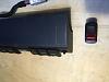
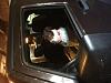
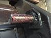
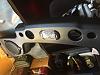
After reading glowing reviews of the Bearcat I decided to go with it over some of the smaller options. This left me with a challenge in finding a mounting location for it. I was all but convinced the the passenger side leg well was going to end up being home but didn't how much it interfered with the seat movement forward. I ended up mounting it to the speaker bar instead and purchased a bluetooth mic to eliminate the cord issue. I couldn't be happier. I can even see my radio face in the rear view mirror and it does not obstruct the view out the back. The only downside to this mount is you need to teach yourself to read backward if you want to use your CB's display, but for the most part that is a "set it and forget it" kind of thing, so it has not been an issue yet.
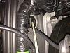
The mounting was simple. I removed the speaker bar and pulled it into the shop. Remove the dome light and drilled two holes where I wanted to put the mount. After that I replaced the speaker bar and ran my wires. I routed my wires through the speaker bar, along the driver side roll bar and down through the molding out through the firewall along the same route as the sPod wires. Then I connected it directly to the battery. I ran my antenna through the tailgate, along the passenger side of the tub, up the roll bar and into the speaker bar. I have had no problems with reception or transmission.
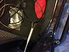
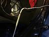
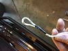
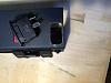
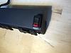
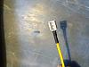
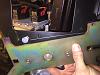
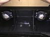
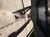
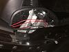
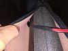
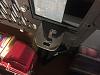
Installing the flush mount antenna was little more difficult. The only spot on the tailgate I could access was right by the handle. I would have preferred a tub mount, but anywhere that thing would fit looked like it might interfere with the rear glass movement or appeared vulnerable to the sides. So, I popped off the little plastic inside the tailgate and placed my backplate to determine my where my holes needed to be drilled. The mounting was simple as you can see and it feels sturdy. Don't forget to stuff some paper or t-shirts into the bottom portion of the tailgate while you're getting everything set up. It turns out you'll have to remove your tailgate to shake loose anything you drop down between the inner structures. Ask me how I know... :(
The mounting was simple. I removed the speaker bar and pulled it into the shop. Remove the dome light and drilled two holes where I wanted to put the mount. After that I replaced the speaker bar and ran my wires. I routed my wires through the speaker bar, along the driver side roll bar and down through the molding out through the firewall along the same route as the sPod wires. Then I connected it directly to the battery. I ran my antenna through the tailgate, along the passenger side of the tub, up the roll bar and into the speaker bar. I have had no problems with reception or transmission.
Installing the flush mount antenna was little more difficult. The only spot on the tailgate I could access was right by the handle. I would have preferred a tub mount, but anywhere that thing would fit looked like it might interfere with the rear glass movement or appeared vulnerable to the sides. So, I popped off the little plastic inside the tailgate and placed my backplate to determine my where my holes needed to be drilled. The mounting was simple as you can see and it feels sturdy. Don't forget to stuff some paper or t-shirts into the bottom portion of the tailgate while you're getting everything set up. It turns out you'll have to remove your tailgate to shake loose anything you drop down between the inner structures. Ask me how I know... :(
10-31-2015, 07:39 PM
#10
JK Enthusiast
Thread Starter
Join Date: May 2013
Location: Utah
Posts: 264
Likes: 0
Received 0 Likes
on
0 Posts
Today I installed my grille insert. I had to manufacture my own little brackets to hold my light bar since it is not a Rigid light. Other than that the install was super easy. The kit came with great instructions and everything fit perfectly.
Still can't figure out how to get my pictures to upload correctly. Don't have the patience to fix it yet.
Still can't figure out how to get my pictures to upload correctly. Don't have the patience to fix it yet.