Currie Enterprises Rear Antirock Write-Up
 06-13-2014, 04:51 PM
#1
JK Junkie
Thread Starter
Currie Enterprises® JK Antirock® Rear Sway Bar Kit W/Aluminum Arms Write-Up
2 DOOR MODEL
Part # CE-9900JKRA
$529.95-Aluminum
4 DOOR MODEL
Part # CE-9900JKR4A
$529.95-Aluminum
Description
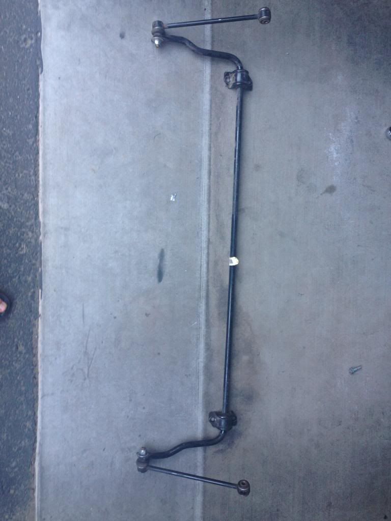
For all 2 door models of the '07 and up Jeep JK Wranglers. The Currie Antirock® rear sway bar kit, when used in conjunction with a front Antirock® sway bar kit, provides balanced performance of front and rear suspension for rugged off-road conditions. It gives the driver increased traction by balancing and distributing the weight and traction over all four tires. The Antirock® off road sway bar is designed to directly replace the stock Jeep sway bar. This bar is made of SAE 4130 heat treated steel for ultimate strength, which is the same quality used in professional off-road competition sway bars. This kit includes all components for installation including, the sway bar, semi-gloss black powder coated bolt-on steel frame brackets, delron bushings, billet aluminum arms, adjustable length heim jointed sway bar links, long travel stainless braided brake lines that relocate the brake line inboard of the frame for sway bar arm clearance, necessary hardware, and step-by-step instructions. Unit bolts into existing holes in the bottom of the frame rail and attaches to the stock mounts on the vehicle's axle housing. The Currie Antirock® sway bar does not need to be disconnected for off-road use.
CAUTION
Jeeps will have more body roll than stock. This sway bar may be used on the street, however, it will not provide the same handling characteristics as the stock setup.
My thoughts
I have been running aftermarket extended rear sway links now for about 2 years. The links have worked perfect this entire time but I decided to finally upgrade to the Currie Enterprises® Rear Antirocks®. After reading multiple reviews online and having their front setup, I decided it was time to have their complete set of front and rear Antirocks®. I chose the aluminum arms not only because of the weight difference, but because the aluminum will match my front Antirocks® and some of the accent pieces on my Jeep. After receiving the new rear Antirocks®, I was curious how the Jeep would handle from stock to completely disconnected. I removed the factory anti-sway setup prior to install and drove the Jeep a full day, and I actually prefer how the Jeep felt completely disconnected compared to being connected. Once the installation was completed, I test drove the Jeep and the rear felt very similar to disconnected, but more secure and stable. I am very pleased with Currie Enterprises® front and rear Antirocks® and I am glad I decided to go with their setup. I would highly recommend their Antirocks® to anyone that is looking to upgrade their front or rear setup for the ultimate balance and traction off road.
Install Rating
The install was pretty easy, but I did have help from Jason at Absolute Offroad® here in Phoenix. If this was your first time installing and all you had was Currie Enterprises® instructions I would lean more towards moderate. Hopefully with this write-up it will be easy for you as well
Install Time
2-4 hours
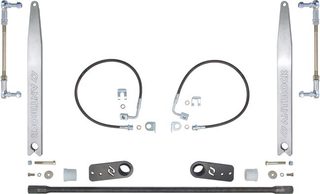
The Currie Enterprises® Rear Antirock® Kit Includes
(1) 50” Antirock® Bar (2 door) CE-9900JR2-BAR
(1) Rear Mounting Bracket (R) CE-9900JKR-BR
(1) Rear Mounting Bracket (L) CE-9900JKR-BL
(1) Brake Line Kit (R/L) CE-9807RBLK
(2) Antirock® Aluminum Arms (R/L) CE-9900-JKRA
(2) Antirock® Bushings (R/L) CE-9901D
(2) 5/16”-24 x ľ“Bolt (R/L) EE-3212CH8
(2) 5/16” Washers (R/L) EE-3120WFZY
(2) 5/16” Lock Washers (R/L) EE-62WS
(2) 3/8”-24 X 2˝” Bolts (R/L) EE-3840CH8
(2) 3/8”-24 Nylock Nuts (R/L) EE-38NS
(2) Sway Bar End Link Rod EE-991050
(2) Sway Bar End Link Rod End Heim Joint (RH) CE-99006
(2) Sway Bar End Link Rod End Heim Joint (LH) CE-99006L
(4) ˝”-20 Nylock Nuts EE-51NS
(2) ˝”-20 Jam Nuts (RH Thread) EE-51NF
(2) ˝”-20 Jam Nuts (LH Thread) EE-51NFLHP
Tools Needed
Protective Eyewear
Work Gloves
Ratchet
Torque Wrench
12mm-19mm Sockets
12mm-19mm Wrenches
3/4 Wrench
Rubber Mallet
Dead Blow
Floor Jack
Jack Stands
Wheel Blocks
Snips
Brake Line Forming Tool
Drill
Drill Bits 1/8” to 5/8”
Cut Off Tool
Marker
Black Spray Paint
Angle Finder
Vacuum Plug Ľ”
Fluid Catch
Brake Fluid
Frosty Beverages
Installation Options
Removing rear wheels and shocks will help with the ease of install, but is not a must. I also removed the rear factory anti-sway setup the day before the actual install, but you will normally remove in Step 6. The Ľ” vacuum plugs I put in “Tools Needed” will stop the brake fluid from constantly running. The brake line forming tool also under “Tools Needed” isn’t a must just a helping tool. Both vacuum plug and forming tool can be found at Harbor Freight® for under and around $10.00 and I HIGHLY RECOMMEND them before starting with this install!
Install Guide
Step 1
Park Jeep on level ground.
Step 2
Lightly loosen all wheel lugs.
• Use 3/4 or 19mm socket.
Step 3
Block rear part of front tires.
Step 4
Raise rear end of Jeep with floor jack and slide two jack stands underneath axle.
Step 5
Remove all lugs and both rear wheels/tires and put to the side.
Step 6
Remove the lower factory or aftermarket sway links. (Driver/Passenger)
• Uses both 18mm and 19mm wrenches/sockets at same time to remove nuts and bolts from links.
Step 7
Remove the factory anti-sway arm bracket mounts on both driver/passenger side.
• Use 16mm socket.
• Remove 1 bolt per bracket and only loosen the other two
• Remove the loosened bolt one at a time holding up anti-sway bar so it doesn’t fall to ground or on top of you.
• Keep bolts for Step 14.
Step 8
Remove Shocks. (Driver/Passenger)
• Use 16mm socket for upper.
• Use 18mm socket/wrench for lower.
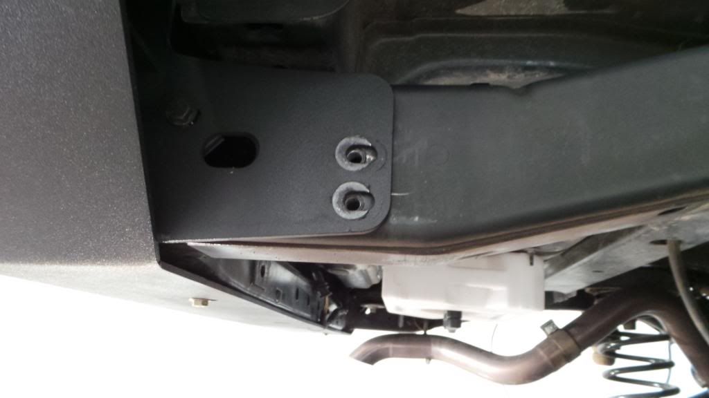
Step 9
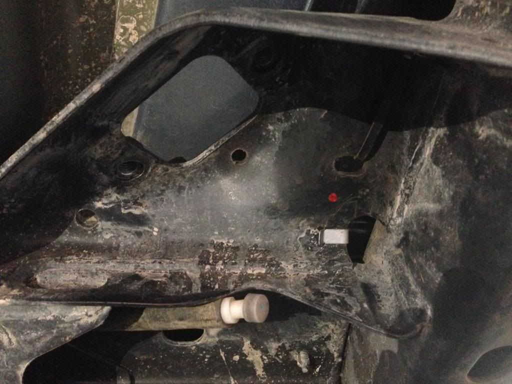
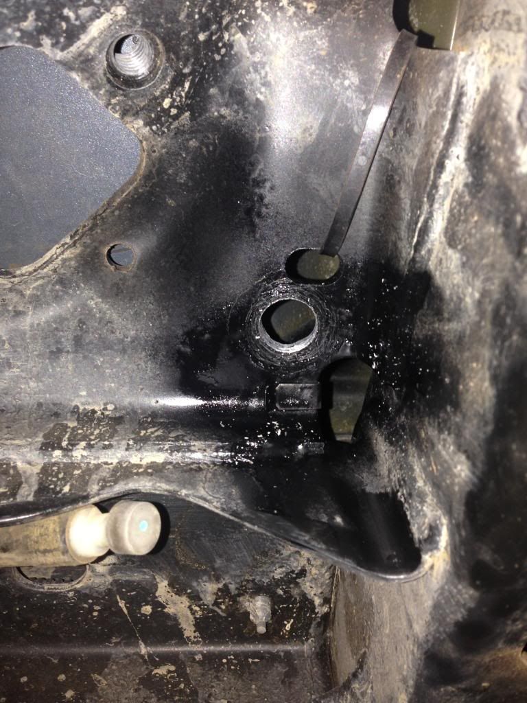
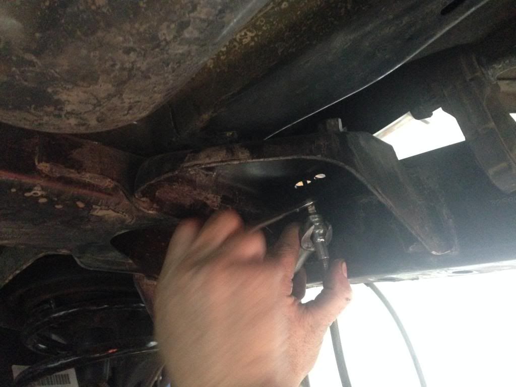
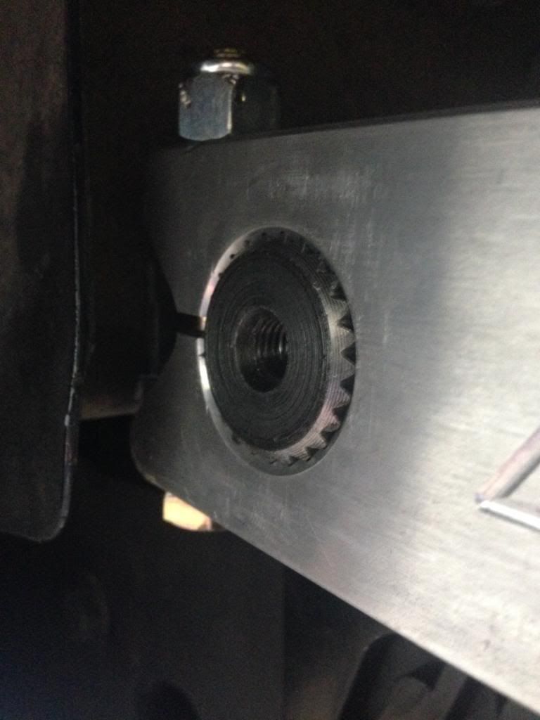
Mark and drill (Driver/Passenger sides) with a 5/8” hole as shown in pictures below.
• Make sure to start with a 1/8” drill bit and work your way up to the 5/8” hole.
• Once holes are drilled make sure to deburr then spray paint raw area.
Step 10
Uninstall upper part of hard brake lines and add the Ľ” vacuum plug to hard line so it doesn’t keep running.
• Make sure you complete one brake line at a time. Then do the same for the other side.
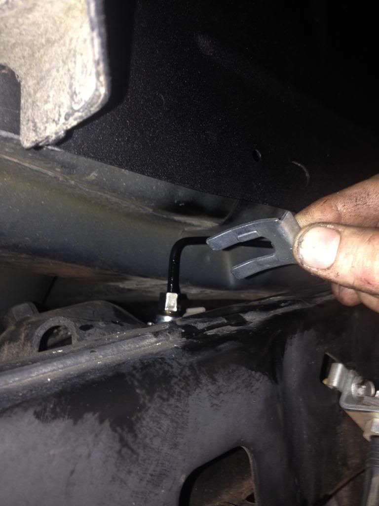
Step 11
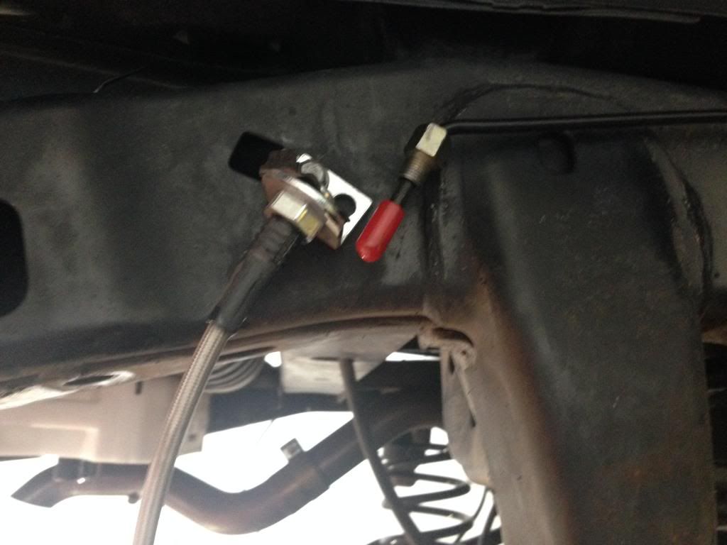
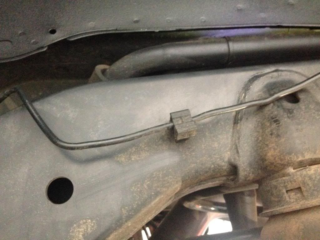
Remove the black plastic hard brake line mount, then bend and form to as straight as possible. Once you have line straightened, add around a 120° angle bend to the end of hard line so it slides through hole you previously drilled on Step 9.
• Make sure you complete one brake line at a time. Then do the same for the other side.
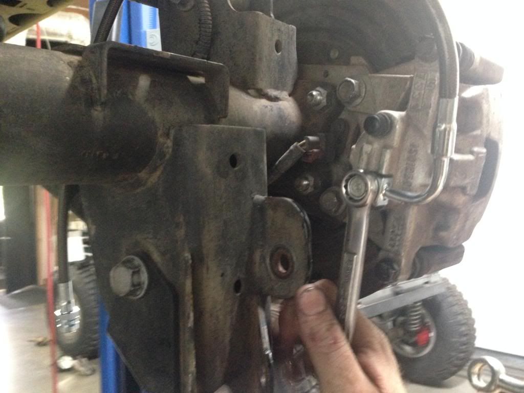
Step 12
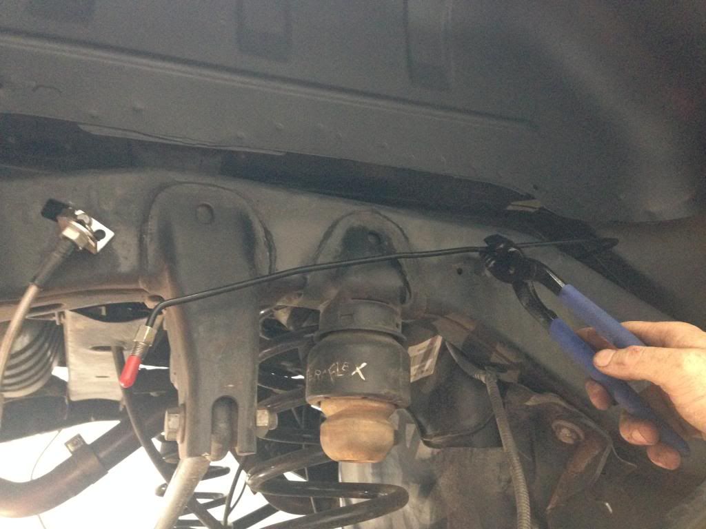
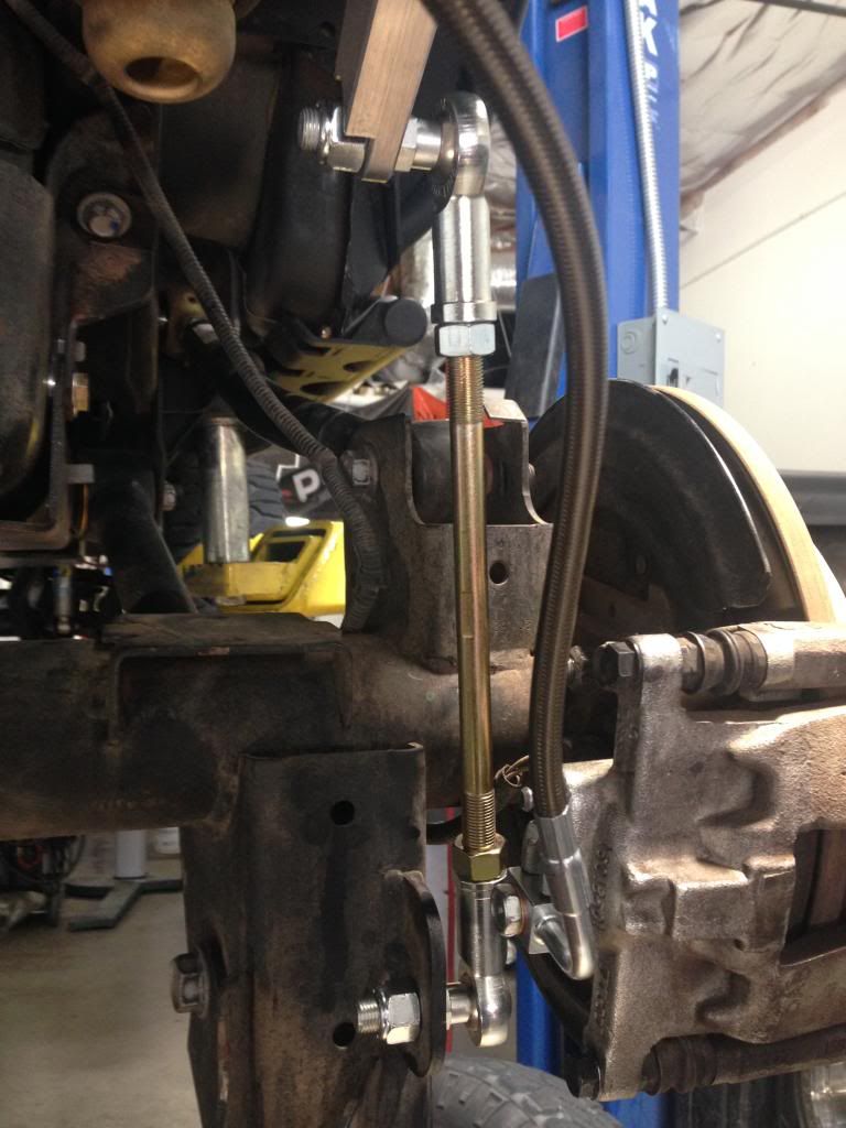
Slide the end of hard brake that you just bent to a 120° through the hole you drilled on Step 9, and install the upper Currie Enterprises® brake line.
• Use 12mm wrench on upper frame nut of line & 17mm wrench for inner part by upper shock mount.
• Make sure to tighten and slide in the mounting clip.
• The brake lines from Currie Enterprises® are right and left. The line must point away from the brake calipers.
• Make sure you complete one brake line at a time. Then do the same for the other side.
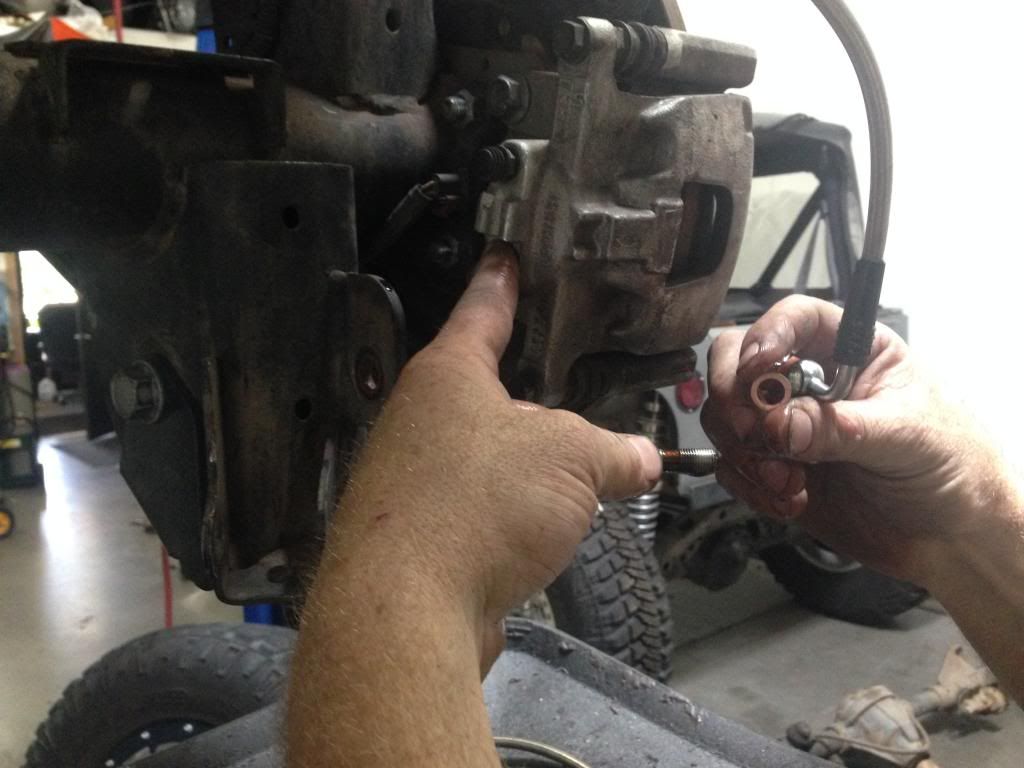
Step 13
Remove factory or aftermarket lower brake line and install the lower part of the Currie Enterprises® line you just installed from the prior step.
• Use 15mm wrench/socket for caliper bolt.
• When installing lower line, make sure you use the new copper washers that are provided!
• To save brake fluid and a mess, put your finger over the hole you just uninstalled the brake line from until you have the lower part of new line ready to install.
• The brake lines are right and left. The line must point away from the brake calipers.
• Make sure you complete one brake line at a time. Then do the same for the passenger side.
Note
Both brake lines should now be straightened, installed through the holes you drilled, and lines should be tightened down on both sides.
• Check for any leaks. If there are leaks coming from new lines, try tightening even more until the leak stops.
• Brake fluid is a very harsh fluid, so any spills or drips need to be cleaned up at this time.
Step 14
FACTORY INSTRUCTIONS
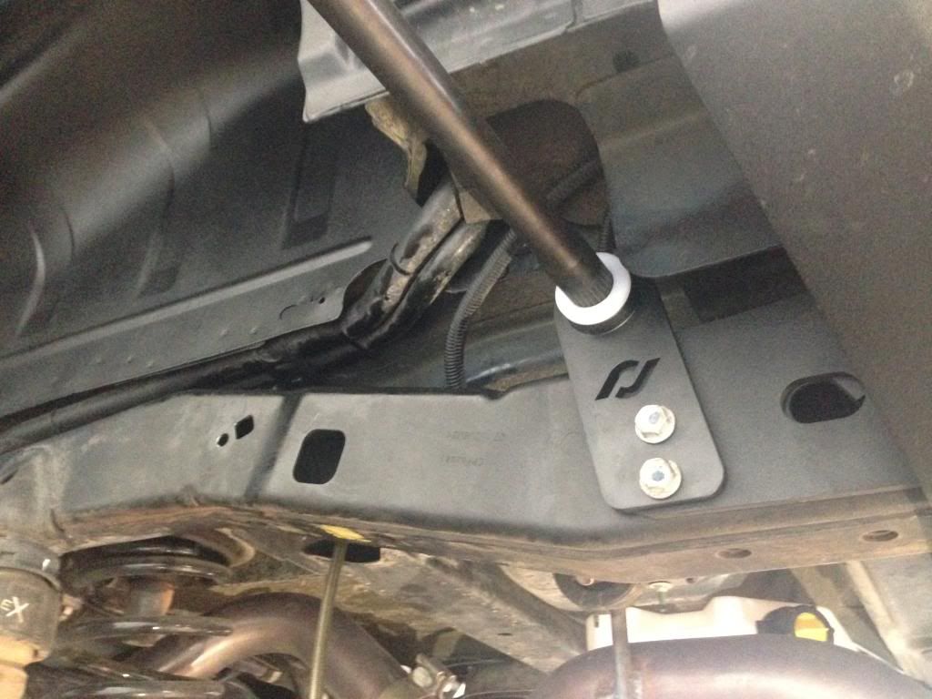
Remove factory bumper support one side at a time. Install the bushings into the Currie Enterprises® mounting bracket then mount bracket back on to frame. The brackets will need to lean towards front of Jeep. (On back side of each bracket they are clearly labeled right/left.)
• Use 16mm socket.
• DO NOT UNBOLT BOTH SIDE OF BUMPER SUPPORTS BEFORE INSTALLING FIRST MOUNTING BRACKET!
• Lip side of bushing should be on outside of bracket.
• You will use the bolts you removed from your factory anti-sway mounts on step 7.
• From frame out- Currie Enterprises® mount, factory bumper support, bolts.

AFTERMARKET BUMPER INSTRUCTIONS
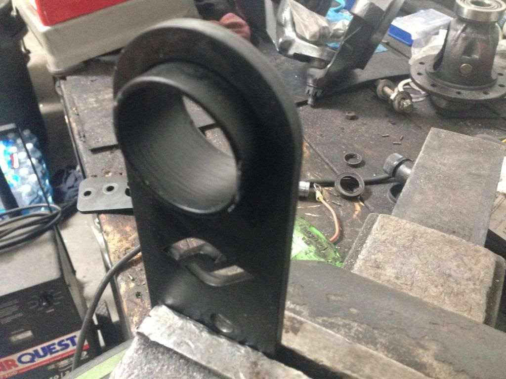
There are some things you will copy from factory instructions but you may need to cut off some of the Currie Enterprises® mounting bracket to fit correct.
Remove the aftermarket bumper support on one side. If your aftermarket bumper bracket goes on the outside of frame, you will need to cut the outboard hub of Currie Enterprises® mounting bracket. If your bumper bracket slides inside of frame you shouldn’t have cut but all bumpers are made different.
• Use 16mm socket.
• DO NOT UNBOLT BOTH SIDE OF BUMPER SUPPORTS BEFORE INSTALLING FIRST MOUNTING BRACKET!
• You will use the bolts you removed from your factory anti-sway mounts on step 7.
I have the Poison Spyder® RockBrawler® II rear bumper, so on my install I had to cut the outboard hub to fit.
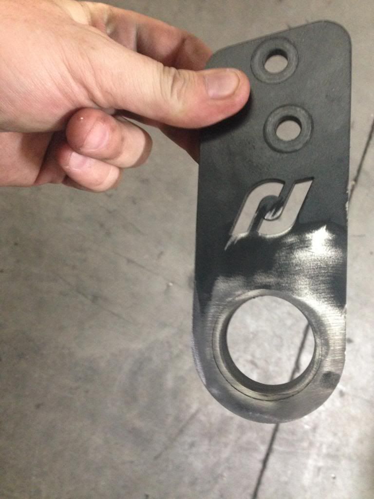
If you have to cut the brackets.
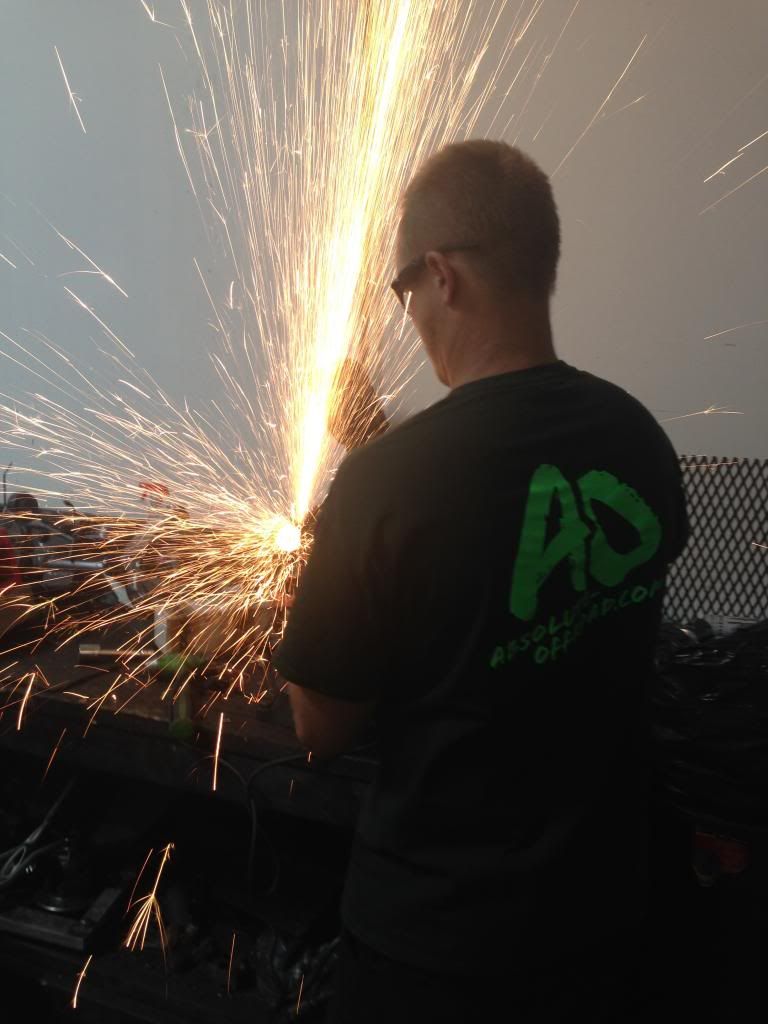
Take your cutting tool and cut off the outboard hub of Currie Enterprises® mounting bracket. Once you have cut/grinded down, clean any burrs off and spray paint black and let dry. Once brackets are dry, slide in the white bushing mount one at a time to bumper supports. (Lip side of bushing should be on outside of bracket.)
• DO NOT CUT ON THE WELDED SIDES!!!
• From frame out- Frame, aftermarket bumper, Currie Enterprises® mount, bolts from step 7.
Step 15
Slide the Antirock® bar through driver side bushing mount until it goes in-between the body and the muffler heat shield from the rear of Jeep and into the bushing/mount of passenger side.
• The Antirock® bar splines need to be equal on both sides of Jeep.
• Rubber mallet/ dead blow and a little lubricant in the bushing can be your best friend.
Step 16
Install the Antirock® arms on both driver/passenger side
• Arms have to be clocked at the exact same on both sides before moving further.
• If Jeep is high enough off the ground, it helps to have your arms straight down to clock.
• You may need to bend out some of the sheet metal of body to make sure the Antirock® arms clear.
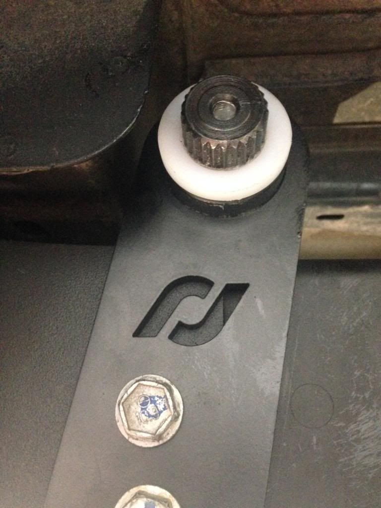
Make sure the spline is long enough that the splines are either sticking out a hair or equal to end of the arms. (This is why you may have to cut your bracket from prior step)
Incorrect way (Before cutting bracket sample)
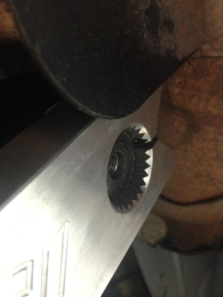
Correct way (After cutting bracket)

Step 17
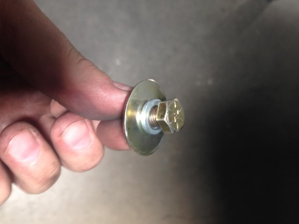
Install the Antirock® arm hardware on both driver/passenger side.
• Use the 3/8”-24 x 2 ˝” Bolts & 3/8”-24 Nylock Nuts.
• I slid bolt through bottom and nut on top to match my front setup.
Step 18
Install the Antirock® bar/arm fasteners on both driver/passenger then tighten down.
• 5/16”-24 x ľ“, 5/16” lock washers, 5/16” washers.
• Use 13mm wrench or socket to tighten down. (Do not over tighten and bend washer)
Step 19
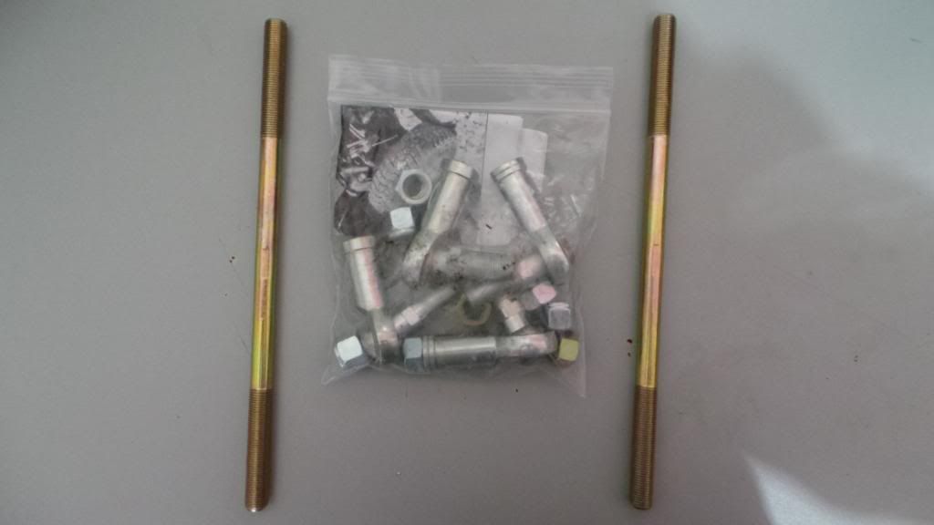
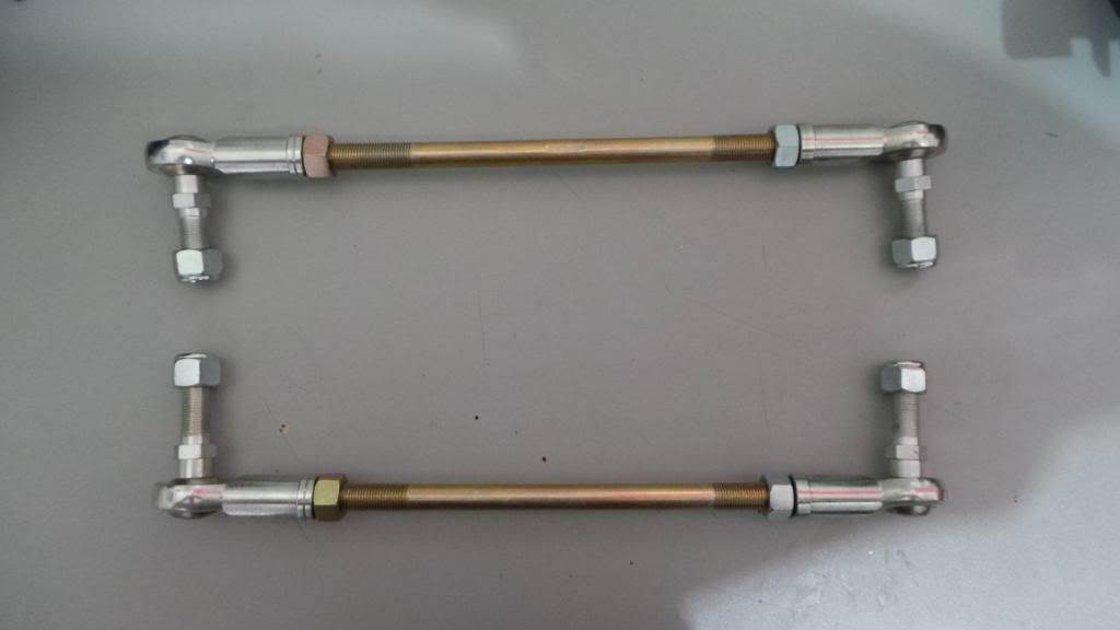
Assemble links
• Screw on the correct LH or RH threaded jam nut on each rod on both sides.
• Screw on the correct LH or RH heim joint to each rod.
• Don’t tighten anything down yet.
• Try to have the threads equal on both sides of each rod.
Step 20
Install the Links to the Antirock® Arms and to the factory lower link mounts on axle.
• Use 19mm wrench for outer heim nut & 16mm for inner part of heim.
Step 21
Reinstall the shocks.
• Use 16mm socket for upper, then torque to 37ft.lbs
• Use 18mm socket and 18mm wrench for lower then torque to 56ft.lbs
Step 22
Reinstall wheels tires and tighten lug nuts.
• Use 3/4 socket or 19mm.
Step 23
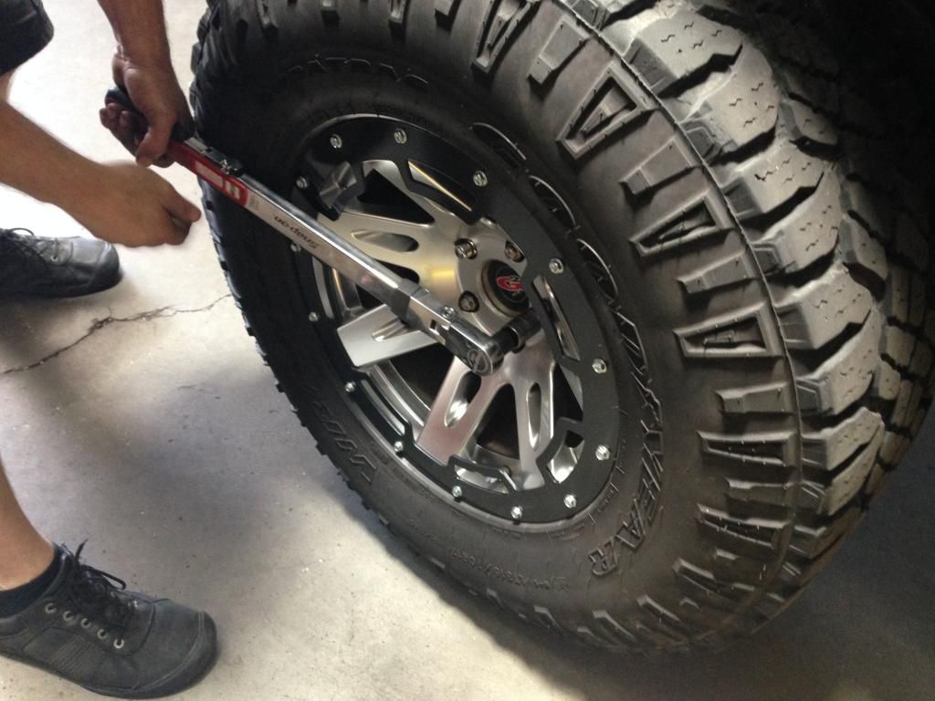
Lift floor jack enough to remove jack stands then remove blocks and lower Jeep to ground.
• Torque all lug nuts to 125ft.lbs using torque wrench and 3/4 socket or 19mm socket.
Step 24
Bleed brakes and check for leaks as well on the new lines.
• See “Owners Manual” for instructions.
CONGRATULATIONS!!!! You are now done with install portion of your Currie Enterprises® Rear Antirocks®.
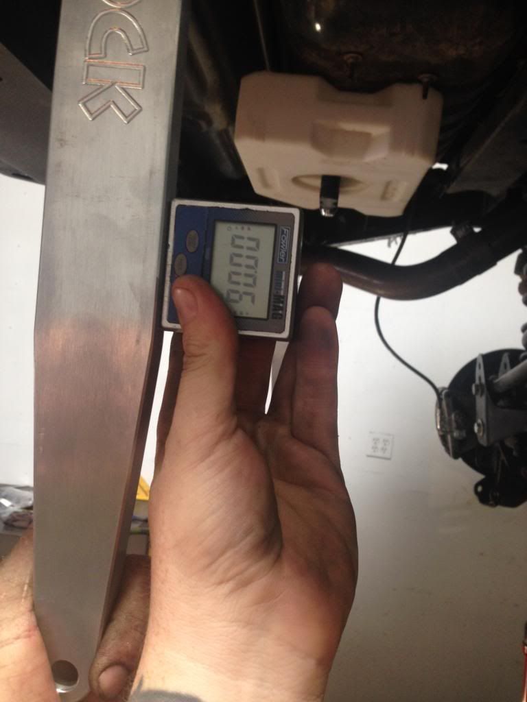
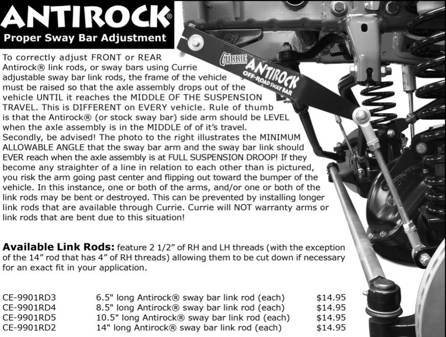
Antirock® Proper Sway Bar Adjustment
NOTE
After 50-100 miles go through your entire install and make sure everything is torqued and tightened down!
Contact Information
Thank you for taking the time to look over my write-up. If you have any questions please feel free to ask on thread or PM. You may also contact me at husker.n.az@gmail.com
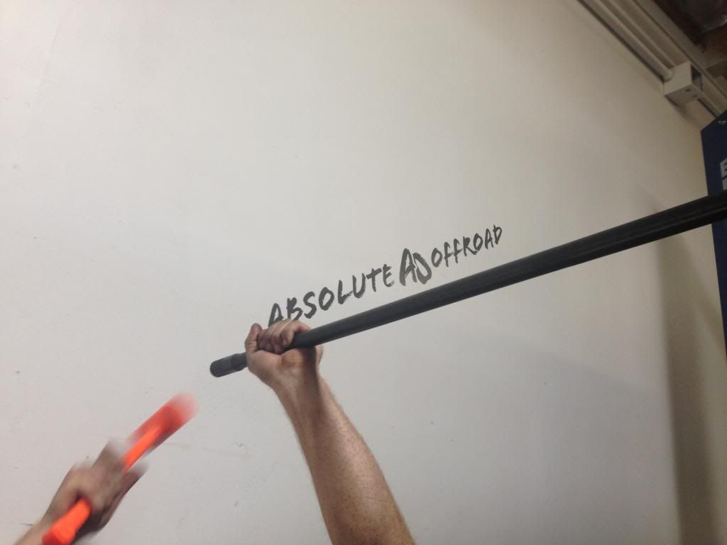
I would also like to thank Jason at Absolute Offroad® for taking the time out of his weekend to help with this install!
Currie Enterprises®
Currie Enterprises - Custom Rearends, Jeep/Off-road Parts, Crate Rearends, 4x4 Rearends
https://www.facebook.com/Currie.Enterprises
Absolute Offroad®
http://www.absolute-offroad.com
https://www.facebook.com/pages/Absol...d/207677171465
My Facebook Pages
http://www.facebook.com/azwranglers
http://www.facebook.com/husker4x4
2 DOOR MODEL
Part # CE-9900JKRA
$529.95-Aluminum
4 DOOR MODEL
Part # CE-9900JKR4A
$529.95-Aluminum
Description
For all 2 door models of the '07 and up Jeep JK Wranglers. The Currie Antirock® rear sway bar kit, when used in conjunction with a front Antirock® sway bar kit, provides balanced performance of front and rear suspension for rugged off-road conditions. It gives the driver increased traction by balancing and distributing the weight and traction over all four tires. The Antirock® off road sway bar is designed to directly replace the stock Jeep sway bar. This bar is made of SAE 4130 heat treated steel for ultimate strength, which is the same quality used in professional off-road competition sway bars. This kit includes all components for installation including, the sway bar, semi-gloss black powder coated bolt-on steel frame brackets, delron bushings, billet aluminum arms, adjustable length heim jointed sway bar links, long travel stainless braided brake lines that relocate the brake line inboard of the frame for sway bar arm clearance, necessary hardware, and step-by-step instructions. Unit bolts into existing holes in the bottom of the frame rail and attaches to the stock mounts on the vehicle's axle housing. The Currie Antirock® sway bar does not need to be disconnected for off-road use.
CAUTION
Jeeps will have more body roll than stock. This sway bar may be used on the street, however, it will not provide the same handling characteristics as the stock setup.
My thoughts
I have been running aftermarket extended rear sway links now for about 2 years. The links have worked perfect this entire time but I decided to finally upgrade to the Currie Enterprises® Rear Antirocks®. After reading multiple reviews online and having their front setup, I decided it was time to have their complete set of front and rear Antirocks®. I chose the aluminum arms not only because of the weight difference, but because the aluminum will match my front Antirocks® and some of the accent pieces on my Jeep. After receiving the new rear Antirocks®, I was curious how the Jeep would handle from stock to completely disconnected. I removed the factory anti-sway setup prior to install and drove the Jeep a full day, and I actually prefer how the Jeep felt completely disconnected compared to being connected. Once the installation was completed, I test drove the Jeep and the rear felt very similar to disconnected, but more secure and stable. I am very pleased with Currie Enterprises® front and rear Antirocks® and I am glad I decided to go with their setup. I would highly recommend their Antirocks® to anyone that is looking to upgrade their front or rear setup for the ultimate balance and traction off road.
Install Rating
The install was pretty easy, but I did have help from Jason at Absolute Offroad® here in Phoenix. If this was your first time installing and all you had was Currie Enterprises® instructions I would lean more towards moderate. Hopefully with this write-up it will be easy for you as well
Install Time
2-4 hours
The Currie Enterprises® Rear Antirock® Kit Includes
(1) 50” Antirock® Bar (2 door) CE-9900JR2-BAR
(1) Rear Mounting Bracket (R) CE-9900JKR-BR
(1) Rear Mounting Bracket (L) CE-9900JKR-BL
(1) Brake Line Kit (R/L) CE-9807RBLK
(2) Antirock® Aluminum Arms (R/L) CE-9900-JKRA
(2) Antirock® Bushings (R/L) CE-9901D
(2) 5/16”-24 x ľ“Bolt (R/L) EE-3212CH8
(2) 5/16” Washers (R/L) EE-3120WFZY
(2) 5/16” Lock Washers (R/L) EE-62WS
(2) 3/8”-24 X 2˝” Bolts (R/L) EE-3840CH8
(2) 3/8”-24 Nylock Nuts (R/L) EE-38NS
(2) Sway Bar End Link Rod EE-991050
(2) Sway Bar End Link Rod End Heim Joint (RH) CE-99006
(2) Sway Bar End Link Rod End Heim Joint (LH) CE-99006L
(4) ˝”-20 Nylock Nuts EE-51NS
(2) ˝”-20 Jam Nuts (RH Thread) EE-51NF
(2) ˝”-20 Jam Nuts (LH Thread) EE-51NFLHP
Tools Needed
Protective Eyewear
Work Gloves
Ratchet
Torque Wrench
12mm-19mm Sockets
12mm-19mm Wrenches
3/4 Wrench
Rubber Mallet
Dead Blow
Floor Jack
Jack Stands
Wheel Blocks
Snips
Brake Line Forming Tool
Drill
Drill Bits 1/8” to 5/8”
Cut Off Tool
Marker
Black Spray Paint
Angle Finder
Vacuum Plug Ľ”
Fluid Catch
Brake Fluid
Frosty Beverages
Installation Options
Removing rear wheels and shocks will help with the ease of install, but is not a must. I also removed the rear factory anti-sway setup the day before the actual install, but you will normally remove in Step 6. The Ľ” vacuum plugs I put in “Tools Needed” will stop the brake fluid from constantly running. The brake line forming tool also under “Tools Needed” isn’t a must just a helping tool. Both vacuum plug and forming tool can be found at Harbor Freight® for under and around $10.00 and I HIGHLY RECOMMEND them before starting with this install!
Install Guide
Step 1
Park Jeep on level ground.
Step 2
Lightly loosen all wheel lugs.
• Use 3/4 or 19mm socket.
Step 3
Block rear part of front tires.
Step 4
Raise rear end of Jeep with floor jack and slide two jack stands underneath axle.
Step 5
Remove all lugs and both rear wheels/tires and put to the side.
Step 6
Remove the lower factory or aftermarket sway links. (Driver/Passenger)
• Uses both 18mm and 19mm wrenches/sockets at same time to remove nuts and bolts from links.
Step 7
Remove the factory anti-sway arm bracket mounts on both driver/passenger side.
• Use 16mm socket.
• Remove 1 bolt per bracket and only loosen the other two
• Remove the loosened bolt one at a time holding up anti-sway bar so it doesn’t fall to ground or on top of you.
• Keep bolts for Step 14.
Step 8
Remove Shocks. (Driver/Passenger)
• Use 16mm socket for upper.
• Use 18mm socket/wrench for lower.
Step 9
Mark and drill (Driver/Passenger sides) with a 5/8” hole as shown in pictures below.
• Make sure to start with a 1/8” drill bit and work your way up to the 5/8” hole.
• Once holes are drilled make sure to deburr then spray paint raw area.
Step 10
Uninstall upper part of hard brake lines and add the Ľ” vacuum plug to hard line so it doesn’t keep running.
• Make sure you complete one brake line at a time. Then do the same for the other side.
Step 11
Remove the black plastic hard brake line mount, then bend and form to as straight as possible. Once you have line straightened, add around a 120° angle bend to the end of hard line so it slides through hole you previously drilled on Step 9.
• Make sure you complete one brake line at a time. Then do the same for the other side.
Step 12
Slide the end of hard brake that you just bent to a 120° through the hole you drilled on Step 9, and install the upper Currie Enterprises® brake line.
• Use 12mm wrench on upper frame nut of line & 17mm wrench for inner part by upper shock mount.
• Make sure to tighten and slide in the mounting clip.
• The brake lines from Currie Enterprises® are right and left. The line must point away from the brake calipers.
• Make sure you complete one brake line at a time. Then do the same for the other side.
Step 13
Remove factory or aftermarket lower brake line and install the lower part of the Currie Enterprises® line you just installed from the prior step.
• Use 15mm wrench/socket for caliper bolt.
• When installing lower line, make sure you use the new copper washers that are provided!
• To save brake fluid and a mess, put your finger over the hole you just uninstalled the brake line from until you have the lower part of new line ready to install.
• The brake lines are right and left. The line must point away from the brake calipers.
• Make sure you complete one brake line at a time. Then do the same for the passenger side.
Note
Both brake lines should now be straightened, installed through the holes you drilled, and lines should be tightened down on both sides.
• Check for any leaks. If there are leaks coming from new lines, try tightening even more until the leak stops.
• Brake fluid is a very harsh fluid, so any spills or drips need to be cleaned up at this time.
Step 14
FACTORY INSTRUCTIONS
Remove factory bumper support one side at a time. Install the bushings into the Currie Enterprises® mounting bracket then mount bracket back on to frame. The brackets will need to lean towards front of Jeep. (On back side of each bracket they are clearly labeled right/left.)
• Use 16mm socket.
• DO NOT UNBOLT BOTH SIDE OF BUMPER SUPPORTS BEFORE INSTALLING FIRST MOUNTING BRACKET!
• Lip side of bushing should be on outside of bracket.
• You will use the bolts you removed from your factory anti-sway mounts on step 7.
• From frame out- Currie Enterprises® mount, factory bumper support, bolts.
AFTERMARKET BUMPER INSTRUCTIONS
There are some things you will copy from factory instructions but you may need to cut off some of the Currie Enterprises® mounting bracket to fit correct.
Remove the aftermarket bumper support on one side. If your aftermarket bumper bracket goes on the outside of frame, you will need to cut the outboard hub of Currie Enterprises® mounting bracket. If your bumper bracket slides inside of frame you shouldn’t have cut but all bumpers are made different.
• Use 16mm socket.
• DO NOT UNBOLT BOTH SIDE OF BUMPER SUPPORTS BEFORE INSTALLING FIRST MOUNTING BRACKET!
• You will use the bolts you removed from your factory anti-sway mounts on step 7.
I have the Poison Spyder® RockBrawler® II rear bumper, so on my install I had to cut the outboard hub to fit.
If you have to cut the brackets.
Take your cutting tool and cut off the outboard hub of Currie Enterprises® mounting bracket. Once you have cut/grinded down, clean any burrs off and spray paint black and let dry. Once brackets are dry, slide in the white bushing mount one at a time to bumper supports. (Lip side of bushing should be on outside of bracket.)
• DO NOT CUT ON THE WELDED SIDES!!!
• From frame out- Frame, aftermarket bumper, Currie Enterprises® mount, bolts from step 7.
Step 15
Slide the Antirock® bar through driver side bushing mount until it goes in-between the body and the muffler heat shield from the rear of Jeep and into the bushing/mount of passenger side.
• The Antirock® bar splines need to be equal on both sides of Jeep.
• Rubber mallet/ dead blow and a little lubricant in the bushing can be your best friend.
Step 16
Install the Antirock® arms on both driver/passenger side
• Arms have to be clocked at the exact same on both sides before moving further.
• If Jeep is high enough off the ground, it helps to have your arms straight down to clock.
• You may need to bend out some of the sheet metal of body to make sure the Antirock® arms clear.
Make sure the spline is long enough that the splines are either sticking out a hair or equal to end of the arms. (This is why you may have to cut your bracket from prior step)
Incorrect way (Before cutting bracket sample)
Correct way (After cutting bracket)
Step 17
Install the Antirock® arm hardware on both driver/passenger side.
• Use the 3/8”-24 x 2 ˝” Bolts & 3/8”-24 Nylock Nuts.
• I slid bolt through bottom and nut on top to match my front setup.
Step 18
Install the Antirock® bar/arm fasteners on both driver/passenger then tighten down.
• 5/16”-24 x ľ“, 5/16” lock washers, 5/16” washers.
• Use 13mm wrench or socket to tighten down. (Do not over tighten and bend washer)
Step 19
Assemble links
• Screw on the correct LH or RH threaded jam nut on each rod on both sides.
• Screw on the correct LH or RH heim joint to each rod.
• Don’t tighten anything down yet.
• Try to have the threads equal on both sides of each rod.
Step 20
Install the Links to the Antirock® Arms and to the factory lower link mounts on axle.
• Use 19mm wrench for outer heim nut & 16mm for inner part of heim.
Step 21
Reinstall the shocks.
• Use 16mm socket for upper, then torque to 37ft.lbs
• Use 18mm socket and 18mm wrench for lower then torque to 56ft.lbs
Step 22
Reinstall wheels tires and tighten lug nuts.
• Use 3/4 socket or 19mm.
Step 23
Lift floor jack enough to remove jack stands then remove blocks and lower Jeep to ground.
• Torque all lug nuts to 125ft.lbs using torque wrench and 3/4 socket or 19mm socket.
Step 24
Bleed brakes and check for leaks as well on the new lines.
• See “Owners Manual” for instructions.
CONGRATULATIONS!!!! You are now done with install portion of your Currie Enterprises® Rear Antirocks®.
Antirock® Proper Sway Bar Adjustment
NOTE
After 50-100 miles go through your entire install and make sure everything is torqued and tightened down!
Contact Information
Thank you for taking the time to look over my write-up. If you have any questions please feel free to ask on thread or PM. You may also contact me at husker.n.az@gmail.com
I would also like to thank Jason at Absolute Offroad® for taking the time out of his weekend to help with this install!
Currie Enterprises®
Currie Enterprises - Custom Rearends, Jeep/Off-road Parts, Crate Rearends, 4x4 Rearends
https://www.facebook.com/Currie.Enterprises
Absolute Offroad®
http://www.absolute-offroad.com
https://www.facebook.com/pages/Absol...d/207677171465
My Facebook Pages
http://www.facebook.com/azwranglers
http://www.facebook.com/husker4x4
Last edited by Hskr4x4; 06-16-2014 at 05:55 PM.
 06-13-2014, 07:11 PM
#3
JK Junkie
Thread Starter
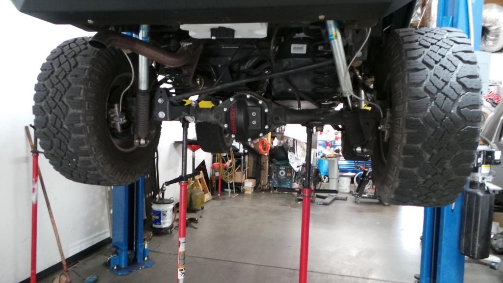
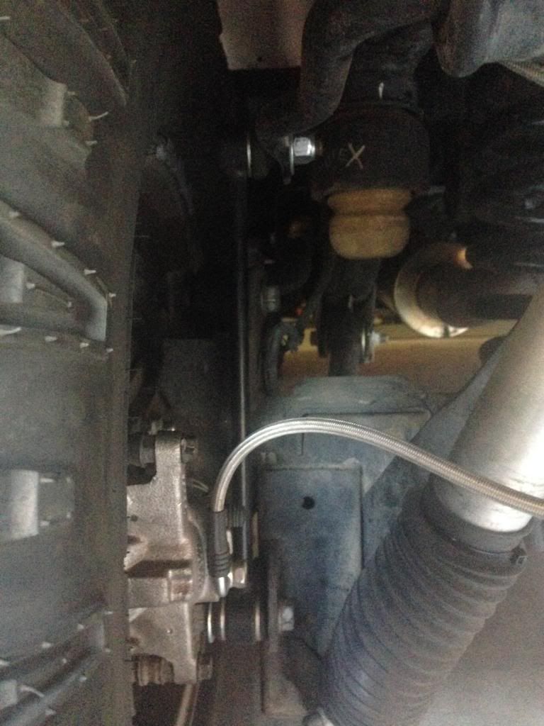
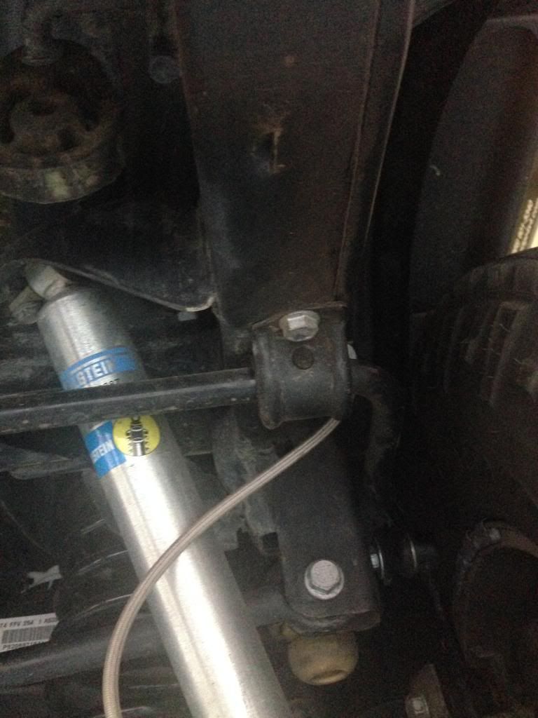
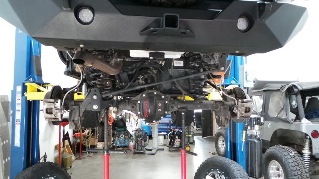
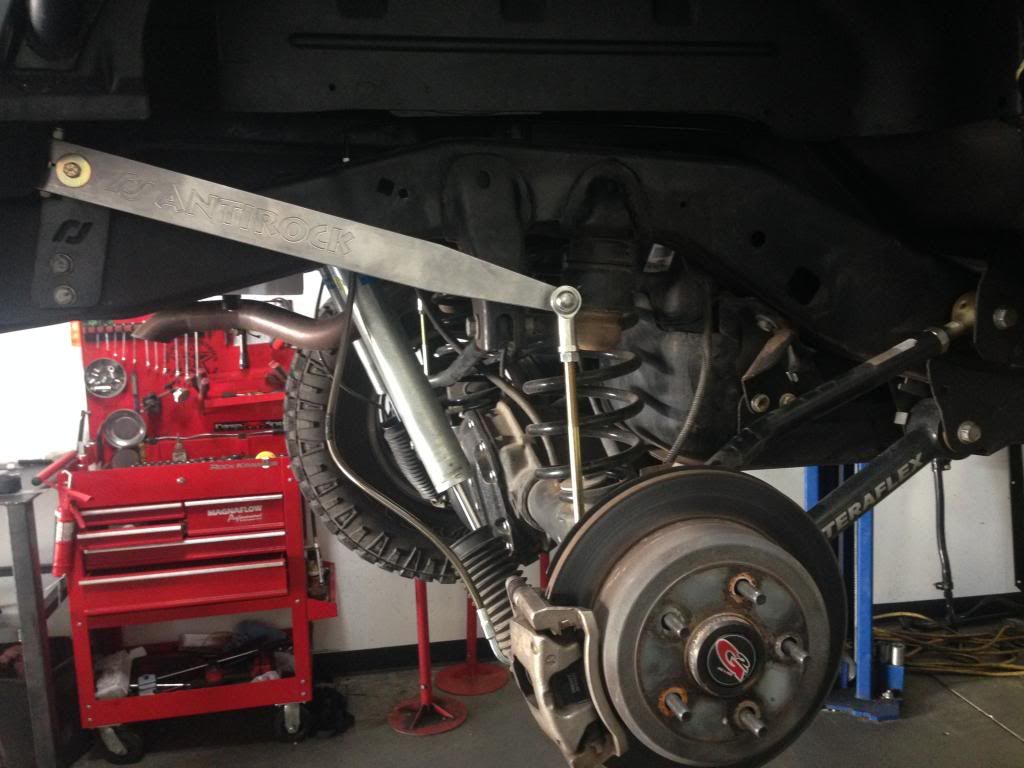
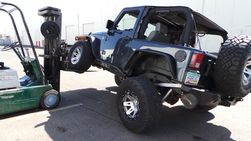
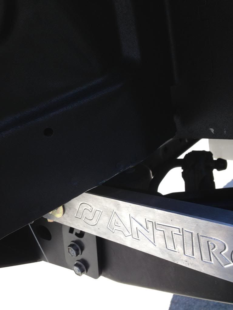
Here are some photos after I adjusted links.
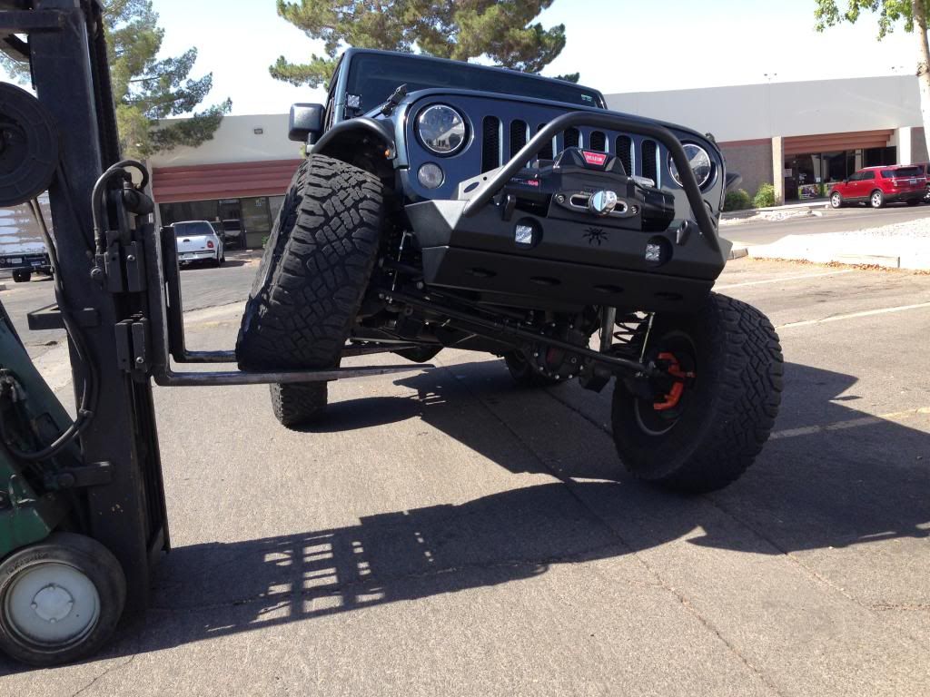
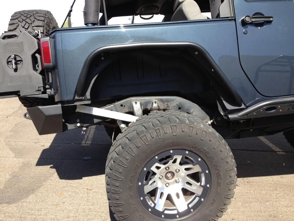
After looking at the adjustments I noticed that rear inner tub on passenger side was really close to hitting arm, so we trimmed a little. You wont have to do this though on driver side since it is already cut back for the gas lines.
After looking at the adjustments I noticed that rear inner tub on passenger side was really close to hitting arm, so we trimmed a little. You wont have to do this though on driver side since it is already cut back for the gas lines.
Last edited by Hskr4x4; 06-13-2014 at 07:18 PM.
06-13-2014, 07:32 PM
#4
JK Newbie
Join Date: May 2012
Location: Dallas, Texas
Posts: 63
Likes: 0
Received 0 Likes
on
0 Posts
Another great write up. Thanks for the effort. My kit should be here by mid-week and I'll be having a local shop do the install since I don't have the tools necessary to deal with brake lines etc. I've been invited to hang out at the shop during the install and I'll do just that so I can see the process and learn as much as possible.
06-13-2014, 07:39 PM
#5
JK Junkie
Thread Starter
Very cool! Post up pics once installed! If they have a fork lift, do the same testings and check passenger tub to make sure arm isn't hitting where I cut
06-15-2014, 08:11 AM
#7
JK Junkie
Thread Starter
Trending Topics
06-15-2014, 08:13 AM
#8
JK Junkie
Thread Starter
Here is the front write-up for anyone looking
https://www.jk-forum.com/forums/jk-w...ar-kit-304126/
^^click^^
https://www.jk-forum.com/forums/jk-w...ar-kit-304126/
^^click^^
06-15-2014, 03:07 PM
#10
JK Junkie
Thread Starter