
hello. why cant i see pics?

Eternal ***erator
Joined: Oct 2006
Posts: 18,270
Likes: 3
From: Niagara, New York
The site the pictures are hosted on might possibly be unavailable to your computer. If you are at work it is possible those sites are blocked by IT, this is very common & thier is little that can be done about it. Sometimes people post the pictures in error and no one can see them. If you can give a specific thread where you are having trouble it may be more helpfull in trying to figure it out.

Thread Starter
JK Enthusiast
Joined: Sep 2009
Posts: 139
Likes: 0
From: Salem, VA
https://www.jk-forum.com/forums/sponsoring-manufacturers-vendors-check-out-cyber-monday-specials-24/official-cop4x4-nack-doors-build-100196/
In this thread on post #1 there should be pictures. I can see them on my cell phone on the mobile site but not on my computer. but on post #31 I can see that picture. Any suggestions? Thanks
In this thread on post #1 there should be pictures. I can see them on my cell phone on the mobile site
but not on my computer. but on post #31 I can see that picture. Any suggestions? Thanks
Eternal ***erator
Joined: Oct 2006
Posts: 18,270
Likes: 3
From: Niagara, New York
In the post you mentioned, the pictures in the first post are hosted here:
http://my.project-jk.com
The Pictures in Post #31 is from a photobucket account.
Can you access my.project-jk.com seperately and view pictures?
I had trouble some time ago with the firewall/adware/antivirus software for some unknown reason not allowing me to view the my.project-jk site, but that was resolved with updates to those programs and replacement of the antivirus software, which exact thing fixed it i cant be sure of, as IT did all three at once.
Are you using any of this type of software? you might need to put in the my.project-jk site as specifically allowed? ~ just a guess but it's worth a shot.
I looked through Evolutions posts, thier pics look to be hosted in a few places, some on photobucket, others here. ~ weird.
I dont think this is a forum issue as you can access in other ways, it looks like something goofy on your computer.
Last edited by HappyCurmudgeon; Sep 24, 2009 at 04:10 AM.
Trending Topics
JK Super Freak
Joined: Feb 2009
Posts: 1,023
Likes: 0
From: Montreal
I've got the same issues and can't figure out what's wrong. In the post below I can't see the pics within the thread. I mean there's nothing at all in place of where the pics are supposed to be. All I can see are the pic links at the end of the thread. Yet on my blackberry I can view everything perfectly 
I tried disabling popupblockers and AVG internet security but that didn't work. Who knows what else I've been missing out on.
Here's what I see;
Attachment 30525
Here's the original post;
I tried disabling popupblockers and AVG internet security but that didn't work. Who knows what else I've been missing out on.
Here's what I see;
Attachment 30525
Here's the original post;
I installed some HID headlights, and hopefully this writeup will help others who want to install them as well. I know it would have saved me some time. I bought an H13 kit from vvme.com, although most of the following should apply to other kits as well. Here's links to a couple of other threads with a lot of information about this, that I found very helpful.
https://www.jk-forum.com/forums/jk-electrical-lighting-sound-systems-13/pics-my-bi-xenons-fogs-92266/
https://www.jk-forum.com/forums/show...95&postcount=2
First of all, here's how everything is basically connected. All of the connectors with the exception of the ring connectors on the power and ground can only be connected one way per headlight, so the connections are pretty straight forward. The relay control module is built into the wiring harness. Here's a link to vvme's page showing the basic connections: http://www.vvme.com/support.jsp
1. The red wire with the ring connector and the inline fuse goes to the positive terminal of the battery.
2. The two black wires with ring connectors go to grounds on the Jeep body.
3. The 3 pin connector that goes to the relay module plugs into one of the Jeep's headlight connectors that previously went to one of the headlights; it doesn't matter which one other than for convenience of routing the HID wiring harness.
4. There are two two pin connectors on the HID wiring harness that plug into each of the ballasts.
5. There are two one pin connectors on the HID wiring harness that plug into each of the headlight bulbs. This controls the high/low beam actuation.
6. There are two pairs of one pin connectors on each ballast that connect to each headlight bulb.
So here's how I installed them.
1. Disconnect the battery ground cable, 10mm wrench required.
2. Remove the grill.
a. Pull out the 6 push pins along the top.
b. Tilt the grill back.
c. Remove the connectors from the turn signals on each side.
d. Pull the grill off.
3. Remove the horn.
a. It's held in place by one Torx screw on the front driver side of the engine compartment. I think it was a T-20 size. I used a 1/4" drive Torx socket.
The screw is on the upper left hand part of the picture.

4. Remove the air filter box.
a. Loosen the clamp on the air intake hose from the airbox cover to the engine.
b. Undo the clips holding the airbox cover on.
c. Move airbox cover out of the way, you can leave the small hose attached.
d. Remove the air filter.
e. Pull the airbox base out. It pulls straight out with a bit of rocking from side to side.
The airbox base just pushes into the 3 rubber grommets in the picture.

5. Move the power steering reservoir out of the way. Use a 10mm socket.
a. Remove the 10mm bolt that holds it in place on the front passenger side of the engine compartment.
b. Move it out of the way behind the radiator. There is no need to disconnect the hoses.
Just the one bolt to undo.

6. Change the bulbs in the headlights.
a. Remove the stock halogen bulbs, just untwist them about 30 degrees and they will pull straight out.
b. Put the new HID bulbs in by reversing the above procedure.
7. Prepare the ballasts for installation. Don't actually install them until after the harness is run and attached to the ballasts.
a. I installed them underneath the headlights from the front of the Jeep (see pictures)
b. I used industrial strength velcro to hold them in place. I think it will be ok. Even if a ballast does somehow come loose, it can't really go anywhere, although it could be damaged by being bounced around. For additional security, you could use the included ballast brackets by drilling a hole in the body mount, and use a self tapping screw to hold the bracket in place.
Driver's side ballast

Passenger's side ballast

8. Modify the wiring harness to prevent the relay from buzzing and the headlights flickering. If you get the warning light canceller, I think this step will be unnecessary, but if you didn't, this step will probably be required. On the kit I received the low beams worked fine, so I only modified the high beam circuit, but the low beam circuit could be modified as well if necessary. You can test this by hooking everything up before actually routing the wiring harness. Also, the relay buzzing problem only seems to occur when the engine is running, so test accordingly. Make sure that everything, power steering reservoir, airbox cover, etc., is out of the way before starting up the engine.
a. On the HID wiring harness that came with the kit, find the 3 pin connector that connects to the kit's relay module.
b. Remove 4 to 6 inches of the tubing around the wires near the connector.
c. The white wire is for the low beams, the blue is the highs, and the brown is the ground.
d. Cut about an inch and a half out of the signal wire, white or blue as necessary, starting an inch or so from the connector.
e. Connect a diode, minimum 25V, 1A to the blue wire with the anode side to the connector. The cathode side, normally indicated by a band around the circumference of the diode, will connect to the other end of the signal wire going to the relay module.
f. Connect a 100uf (microfarad) electrolytic capacitor, minimum 25V between the signal wire where it connects to the cathode of the diode and the brown ground wire. Offset the ground connection by about an inch from the signal wire connection to prevent shorts, see picture. MAKE SURE THAT THE NEGATIVE SIDE OF THE CAPACITOR IS ATTACHED TO THE BROWN GROUND LEAD. An electrolytic capacitor will pop if hooked up backwards (bigger ones go BANG!).
g. Solder the diode and capacitor to the harness.
h. Use electrical tape to individually wrap the signal and ground wires, and then tape around all three wires making sure that any exposed wires are covered.
i. Connect everything up and test that it works correctly. Disconnect the ground cable on the battery when done testing.
j. Install split cable tubing around the part of the harness where the tubing was removed in step b, use zip ties to hold it in place. 1/2" tubing worked well for me.
Connector before mod with tubing removed

Diode and capacitor soldered in

Tubing zip tied over the modified part of the harness

9. Route the wiring harness. I'd recommend not connecting anything until all the wiring is routed where you want it to be, and you've verified that all the connectors will reach to where they need to connect.
a. Start by locating the relay control module where you plan to install it. I put it between the passenger side front fender and the body, see pictures. Route the harness into the engine compartment.
b. Route the red wire with the ring connector to the positive terminal on the battery. Run it along the fender next to the factory wiring harness.
c. The passenger side ground can be connected to an existing body ground, see picture.
d. The passenger side high/low beam control wire should end up near the passenger side headlight.
e. The passenger side ballast connector should be next to the ballast.
f. The rest of the wiring harness should be run to the driver's side of the Jeep near the headlight. Just run it along the large factory wiring harness that runs across in front of the radiator.
g. The driver side ground can be connected to an existing body ground, see picture.
h. The driver side high/low beam control wire should end up near the driver side headlight.
e. The driver side ballast connector should be next to the ballast.
Driver's side ground location

Passenger's side ground location

Wiring harness routing across the front

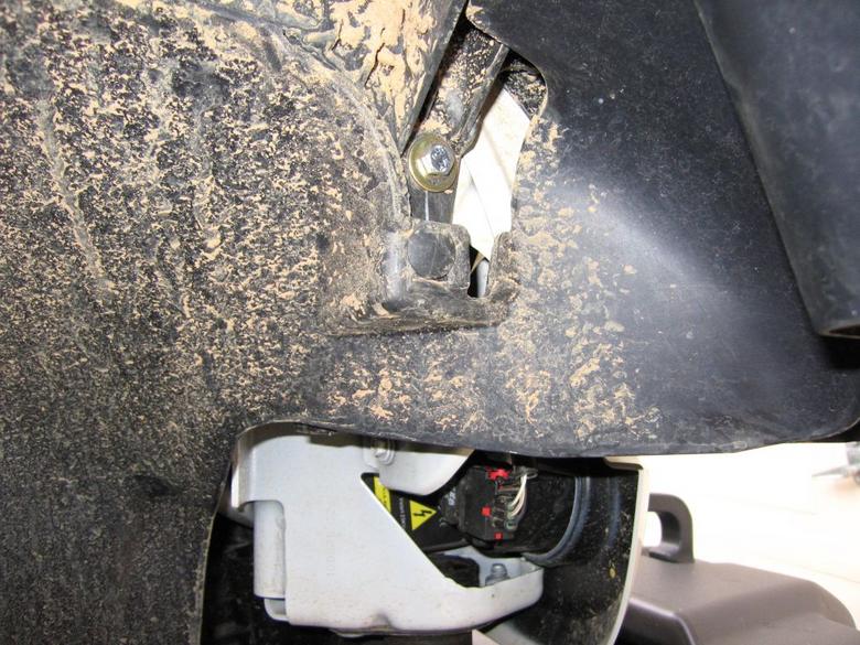
10. Mount the relay control module. Note this is easier to do if you remove the front three or four pins holding the inner fender liner on so that you can move it out of the way.
a. Remove the front fender mounting bolt, see picture.
b. Install a new longer bolt with washer to attach the fender, size 6mm x 1.0, length 20mm.
c. The tab of the relay control module will fit over the back of this bolt, install a lockwasher and nut to hold it on. (On the kit I received, the lockwasher and nut that came with the kit were the correct size.)
The relay module is down here inside the fender
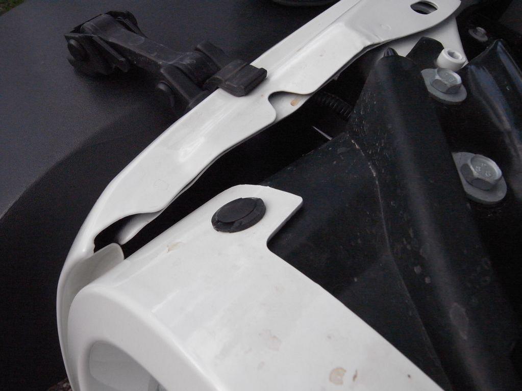
The relay module installed, looking from above

The relay module installed, looking from in front, showing the nut on the tab
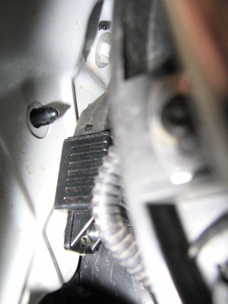
The fender bolt that is replaced to hold the relay module is in the upper center of the picture
11. Connect up the following parts of the wiring harness.
a. The two ballast connectors to each of the ballasts.
b. The ground rings on each side to the body grounds.
c. The high/low beam connectors to each headlight.
12. Install the ballasts.
a. Install the ballasts in their respective locations.
b. Connect the ballast wires to the headlights.
13. Make remaining connections.
a. Connect the three pin relay control connector to the passenger side factory headlight connector.
b. Connect the red power wire with the ring connector to the battery positive terminal; there is an existing bolt holding some other wires on, which can be used.
c. Connect the battery ground cable back to the battery.
14. Test to make sure the headlights work correctly, engine off and on, and high/low beams.
15. Tuck all wiring away and zip tie as necessary.
a. Zip tie the wiring together on the driver side near the headlight and below where the horn will go.
b. Zip tie the wiring together on the passenger side near the headlight, and tuck it in as far forward as possible above the headlight bulb. It will end up between the body and the power steering reservoir.
c. Install zip ties to hold the HID wiring harness across the front to the large factory wiring harness.
d. Use a few more zip ties to hold the HID wiring harness power and ground wires in place.
16. Reinstall parts.
a. Horn
b. Power steering reservoir.
c. Lower airbox.
d. Air filter.
e. Air filter cover. Attach clips and tighten clamp on air intake hose to engine.
17. Enjoy your dramatically brighter headlights.
I think that's about it. Please let me know if there are any errors so that I can correct them, and any suggestions are appreciated as well.
The pictures are of the horn, the power steering reservoir, where the airbox base goes, and where I put the relay control module.
https://www.jk-forum.com/forums/jk-electrical-lighting-sound-systems-13/pics-my-bi-xenons-fogs-92266/
https://www.jk-forum.com/forums/show...95&postcount=2
First of all, here's how everything is basically connected. All of the connectors with the exception of the ring connectors on the power and ground can only be connected one way per headlight, so the connections are pretty straight forward. The relay control module is built into the wiring harness. Here's a link to vvme's page showing the basic connections: http://www.vvme.com/support.jsp
1. The red wire with the ring connector and the inline fuse goes to the positive terminal of the battery.
2. The two black wires with ring connectors go to grounds on the Jeep body.
3. The 3 pin connector that goes to the relay module plugs into one of the Jeep's headlight connectors that previously went to one of the headlights; it doesn't matter which one other than for convenience of routing the HID wiring harness.
4. There are two two pin connectors on the HID wiring harness that plug into each of the ballasts.
5. There are two one pin connectors on the HID wiring harness that plug into each of the headlight bulbs. This controls the high/low beam actuation.
6. There are two pairs of one pin connectors on each ballast that connect to each headlight bulb.
So here's how I installed them.
1. Disconnect the battery ground cable, 10mm wrench required.
2. Remove the grill.
a. Pull out the 6 push pins along the top.
b. Tilt the grill back.
c. Remove the connectors from the turn signals on each side.
d. Pull the grill off.
3. Remove the horn.
a. It's held in place by one Torx screw on the front driver side of the engine compartment. I think it was a T-20 size. I used a 1/4" drive Torx socket.
The screw is on the upper left hand part of the picture.
4. Remove the air filter box.
a. Loosen the clamp on the air intake hose from the airbox cover to the engine.
b. Undo the clips holding the airbox cover on.
c. Move airbox cover out of the way, you can leave the small hose attached.
d. Remove the air filter.
e. Pull the airbox base out. It pulls straight out with a bit of rocking from side to side.
The airbox base just pushes into the 3 rubber grommets in the picture.
5. Move the power steering reservoir out of the way. Use a 10mm socket.
a. Remove the 10mm bolt that holds it in place on the front passenger side of the engine compartment.
b. Move it out of the way behind the radiator. There is no need to disconnect the hoses.
Just the one bolt to undo.
6. Change the bulbs in the headlights.
a. Remove the stock halogen bulbs, just untwist them about 30 degrees and they will pull straight out.
b. Put the new HID bulbs in by reversing the above procedure.
7. Prepare the ballasts for installation. Don't actually install them until after the harness is run and attached to the ballasts.
a. I installed them underneath the headlights from the front of the Jeep (see pictures)
b. I used industrial strength velcro to hold them in place. I think it will be ok. Even if a ballast does somehow come loose, it can't really go anywhere, although it could be damaged by being bounced around. For additional security, you could use the included ballast brackets by drilling a hole in the body mount, and use a self tapping screw to hold the bracket in place.
Driver's side ballast
Passenger's side ballast
8. Modify the wiring harness to prevent the relay from buzzing and the headlights flickering. If you get the warning light canceller, I think this step will be unnecessary, but if you didn't, this step will probably be required. On the kit I received the low beams worked fine, so I only modified the high beam circuit, but the low beam circuit could be modified as well if necessary. You can test this by hooking everything up before actually routing the wiring harness. Also, the relay buzzing problem only seems to occur when the engine is running, so test accordingly. Make sure that everything, power steering reservoir, airbox cover, etc., is out of the way before starting up the engine.
a. On the HID wiring harness that came with the kit, find the 3 pin connector that connects to the kit's relay module.
b. Remove 4 to 6 inches of the tubing around the wires near the connector.
c. The white wire is for the low beams, the blue is the highs, and the brown is the ground.
d. Cut about an inch and a half out of the signal wire, white or blue as necessary, starting an inch or so from the connector.
e. Connect a diode, minimum 25V, 1A to the blue wire with the anode side to the connector. The cathode side, normally indicated by a band around the circumference of the diode, will connect to the other end of the signal wire going to the relay module.
f. Connect a 100uf (microfarad) electrolytic capacitor, minimum 25V between the signal wire where it connects to the cathode of the diode and the brown ground wire. Offset the ground connection by about an inch from the signal wire connection to prevent shorts, see picture. MAKE SURE THAT THE NEGATIVE SIDE OF THE CAPACITOR IS ATTACHED TO THE BROWN GROUND LEAD. An electrolytic capacitor will pop if hooked up backwards (bigger ones go BANG!).
g. Solder the diode and capacitor to the harness.
h. Use electrical tape to individually wrap the signal and ground wires, and then tape around all three wires making sure that any exposed wires are covered.
i. Connect everything up and test that it works correctly. Disconnect the ground cable on the battery when done testing.
j. Install split cable tubing around the part of the harness where the tubing was removed in step b, use zip ties to hold it in place. 1/2" tubing worked well for me.
Connector before mod with tubing removed
Diode and capacitor soldered in
Tubing zip tied over the modified part of the harness
9. Route the wiring harness. I'd recommend not connecting anything until all the wiring is routed where you want it to be, and you've verified that all the connectors will reach to where they need to connect.
a. Start by locating the relay control module where you plan to install it. I put it between the passenger side front fender and the body, see pictures. Route the harness into the engine compartment.
b. Route the red wire with the ring connector to the positive terminal on the battery. Run it along the fender next to the factory wiring harness.
c. The passenger side ground can be connected to an existing body ground, see picture.
d. The passenger side high/low beam control wire should end up near the passenger side headlight.
e. The passenger side ballast connector should be next to the ballast.
f. The rest of the wiring harness should be run to the driver's side of the Jeep near the headlight. Just run it along the large factory wiring harness that runs across in front of the radiator.
g. The driver side ground can be connected to an existing body ground, see picture.
h. The driver side high/low beam control wire should end up near the driver side headlight.
e. The driver side ballast connector should be next to the ballast.
Driver's side ground location
Passenger's side ground location
Wiring harness routing across the front
10. Mount the relay control module. Note this is easier to do if you remove the front three or four pins holding the inner fender liner on so that you can move it out of the way.
a. Remove the front fender mounting bolt, see picture.
b. Install a new longer bolt with washer to attach the fender, size 6mm x 1.0, length 20mm.
c. The tab of the relay control module will fit over the back of this bolt, install a lockwasher and nut to hold it on. (On the kit I received, the lockwasher and nut that came with the kit were the correct size.)
The relay module is down here inside the fender
The relay module installed, looking from above
The relay module installed, looking from in front, showing the nut on the tab
The fender bolt that is replaced to hold the relay module is in the upper center of the picture
11. Connect up the following parts of the wiring harness.
a. The two ballast connectors to each of the ballasts.
b. The ground rings on each side to the body grounds.
c. The high/low beam connectors to each headlight.
12. Install the ballasts.
a. Install the ballasts in their respective locations.
b. Connect the ballast wires to the headlights.
13. Make remaining connections.
a. Connect the three pin relay control connector to the passenger side factory headlight connector.
b. Connect the red power wire with the ring connector to the battery positive terminal; there is an existing bolt holding some other wires on, which can be used.
c. Connect the battery ground cable back to the battery.
14. Test to make sure the headlights work correctly, engine off and on, and high/low beams.
15. Tuck all wiring away and zip tie as necessary.
a. Zip tie the wiring together on the driver side near the headlight and below where the horn will go.
b. Zip tie the wiring together on the passenger side near the headlight, and tuck it in as far forward as possible above the headlight bulb. It will end up between the body and the power steering reservoir.
c. Install zip ties to hold the HID wiring harness across the front to the large factory wiring harness.
d. Use a few more zip ties to hold the HID wiring harness power and ground wires in place.
16. Reinstall parts.
a. Horn
b. Power steering reservoir.
c. Lower airbox.
d. Air filter.
e. Air filter cover. Attach clips and tighten clamp on air intake hose to engine.
17. Enjoy your dramatically brighter headlights.
I think that's about it. Please let me know if there are any errors so that I can correct them, and any suggestions are appreciated as well.
The pictures are of the horn, the power steering reservoir, where the airbox base goes, and where I put the relay control module.
Last edited by MFX; Feb 27, 2010 at 04:47 AM.

JK-Forum Founder
Joined: Sep 2006
Posts: 3,315
Likes: 4
From: OC
