
Adding devices to stock fuse box


Thread Starter
JK Newbie
Joined: Aug 2012
Posts: 38
Likes: 0
From: Seattle, WA
I'm thinking of adding a few lights to my '10 Rubicon. I think it would be easier and cleaner to just run them through the stock fuse box wit the handful of empty slots. I know that the lights I'm looking at come with a single fuse box and there are option like a painless aux fuse box, but I think the stock fuse box will work just fine.
Can anyone direct me to some resources as to how I add a device to the stock fuse box?
Can anyone direct me to some resources as to how I add a device to the stock fuse box?
JK Junkie
Joined: Nov 2008
Posts: 3,297
Likes: 8
From: Cabot, Ar.
I'm thinking of adding a few lights to my '10 Rubicon. I think it would be easier and cleaner to just run them through the stock fuse box wit the handful of empty slots. I know that the lights I'm looking at come with a single fuse box and there are option like a painless aux fuse box, but I think the stock fuse box will work just fine.
Can anyone direct me to some resources as to how I add a device to the stock fuse box?
Can anyone direct me to some resources as to how I add a device to the stock fuse box?
Thread Starter
JK Newbie
Joined: Aug 2012
Posts: 38
Likes: 0
From: Seattle, WA
The circuits under the blank fuse holders are probably just not there. "ronjenx" has an excelent tutorial on the TIPM modual. It would be possible to use his information on the inner workings of the TIPM modual to learn how to load the new circuits. But I wouldn't recommend adding a verry large load to the TIPM modual. This system runs your entire Jeep. Why take a chance and screw it up. To do this project with any confidence. You would need to know the total load carrying capabilities of the TIPM module.
JK Jedi Master

Joined: Feb 2008
Posts: 12,907
Likes: 185
From: Maine
Small loads can be added to the TIPM, without risk to the TIPM.
Here is a picture showing hot and switched spots in the fuse panel on a 2008 TIPM. Other years are very similar.
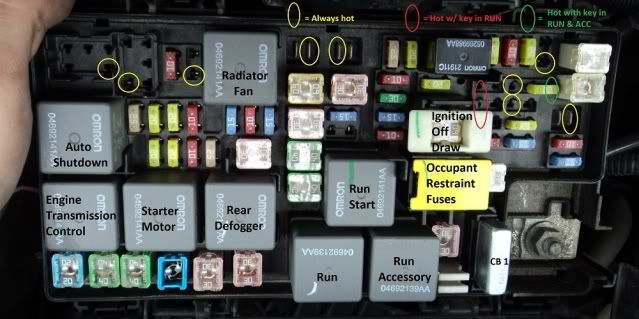
Here are two links showing how to add switched power.
One link shows adding from the top, the other shows adding from underneath.
https://www.jk-forum.com/forums/jk-e...source-191552/
https://www.jk-forum.com/forums/jk-e...source-189556/
Here is a picture showing hot and switched spots in the fuse panel on a 2008 TIPM. Other years are very similar.
Here are two links showing how to add switched power.
One link shows adding from the top, the other shows adding from underneath.
https://www.jk-forum.com/forums/jk-e...source-191552/
https://www.jk-forum.com/forums/jk-e...source-189556/
Thread Starter
JK Newbie
Joined: Aug 2012
Posts: 38
Likes: 0
From: Seattle, WA
Small loads can be added to the TIPM, without risk to the TIPM.
Here is a picture showing hot and switched spots in the fuse panel on a 2008 TIPM. Other years are very similar.
Here are two links showing how to add switched power.
One link shows adding from the top, the other shows adding from underneath.
https://www.jk-forum.com/forums/jk-e...source-191552/
https://www.jk-forum.com/forums/jk-e...source-189556/
My only question is what qualifies as a small load? I mean, one project I'm planning is an LED light in trunk... which I'm pretty sure will be safe. What about wiring aux exterior lights like KC Highlites, like 40 amps?
JK Jedi Master
Joined: Feb 2008
Posts: 12,907
Likes: 185
From: Maine
Very useful! That's exactly what I was looking for... I didn't find it in the search... but didn't know exactly what I was looking for. Thank you!
My only question is what qualifies as a small load? I mean, one project I'm planning is an LED light in trunk... which I'm pretty sure will be safe. What about wiring aux exterior lights like KC Highlites, like 40 amps?
My only question is what qualifies as a small load? I mean, one project I'm planning is an LED light in trunk... which I'm pretty sure will be safe. What about wiring aux exterior lights like KC Highlites, like 40 amps?
You can use the points above to power the control side of a relay.
The heavy load that goes through the relay can be from a fused wire from the battery post.
Last edited by ronjenx; Dec 4, 2012 at 01:50 PM.
Trending Topics
Thread Starter
JK Newbie
Joined: Aug 2012
Posts: 38
Likes: 0
From: Seattle, WA
Alright. Just one last thing; would I need to run a fuse to the lower amperage side of a relay if there's already one on the higher load end before the relay? Or is that like a redundant safeguard thing to be on the safe side?
JK Jedi Master
Joined: Feb 2008
Posts: 12,907
Likes: 185
From: Maine
The high and low sides of the relay are two separate circuits, so they get their own properly rated fuse.