


Connecting relay directly to high beam wire?


JK Jedi
Joined: Apr 2010
Posts: 4,468
Likes: 221
From: SE Michigan

I got the spec sheet on the relay i was using. The coil resistance is +/- 10% @ 23*c(73.4*F) 123 ohms. What i actually got was 104 ohms(it was cold outside too) when i measured it. So by following the fomula from the video i get this. 5 X 10⁴ ohms X .001(1000uf cap) = .52 seconds.
 But how does this tell me what size cap to use??
 However, we're now traveling on the path we need to be going to get you closer to the correct cap size....."IF", there is actually one, where I have my doubts. The (5xRxC) equation is not really useful to us for what you are trying to do, but I'm glad the video showed it, because it got you to thinking of what is going on in this circuit in regards to the Resistance and the Cap value. You see, the (5*R*C) equation, tells you how long it will take for the cap to fully discharge, where we're really not interested in that. A more useful equation for what you are trying to achieve is the (RxC) equation, which is named the RC time constant.
What T(sec)=RxC tells you, is that the Initial fully charged voltage will have dropped by 63% of its initial charged voltage at time "T", in seconds.
I made that initial bigger, because that's a key word of where I'm going.
Here's a graph of a typical Capacitor discharging, just to give you some kind of visual of what is going on, and why this isn't as complicated as it sounds..

Voltage level(V) is on the Y axis and Time (T) is on the X-axis.
See how T=5xRxC the voltage from the cap is fully discharged, and at T=(1xRxC) it is discharged by 63% from its initial charged value?
Hopefully, by now you can start to understand how your additional diode is actually hurting you. You're not allowing the cap to charge up to a higher "initial" voltage than it could be without out.
Now imagine putting a 6 volt regulator in that circuit, and limiting the cap so the initial fully charged voltage can only charge up to 6 volts. You might as well just go shoot yourself in the foot, but I'll wait to hear back from Sahara_Maverick on how well that experiment is going.

Last edited by Rednroll; Apr 4, 2013 at 04:53 AM.

JK Newbie
Joined: May 2011
Posts: 42
Likes: 0
From: Northern NJ
You don't have the "full circuit" diagram shown. Correct me if I'm wrong. Wasn't the original intention of this circuit, to turn on auxiliary lights when the bright lights were turned ON. So that voltage source that is triggering your aux circuit lights, is also powering the JKs main bright head lights at the same time correct? Your circuit diagram doesn't show the existing wiring, which is powering the OE head bright lights.
 I think i hi jacked this tread.
 SORRY for the confusion.
MY intention is to upgrade my IPF H4 headlights bulbs to a higher watt bulb without frying the factory wiring and the Tipm. So i made this relay harness to isolate tipm and the H4 bulbs (it goes in between the factory H13 plug and the H4 bulb).
This is the new diagram. I remove the diode on the ground from the factory H13 plug and put in a jumper.
One relay is powering up both low beams and the other is powering up both hi beams on the IPF headlights.
That wasn't really my intent for asking the minimum voltage value across the coil for knowing what voltage closes the relay. More so to know the minimum voltage level to "keeps it closed". This is a very important piece of information. Thank you for looking it up. We want to try to make sure that relay does not open back up, during the time our capacitor is discharging. So we need to chose the value of the cap "C" so that when it's near its 65% discharge point, the voltage does not drop below 8.4 volts.
So as long as these caps voltage doesnt drop below 1.4 volts this relay should stay closed, as far as the tech sheet says. But we all know there some wiggle room in there too.
Now imagine putting a 6 volt regulator in that circuit, and limiting the cap so the initial fully charged voltage can only charge up to 6 volts. You might as well just go shoot yourself in the foot, but I'll wait to hear back from Sahara_Maverick on how well that experiment is going.

Im going to try some smaller caps to see what happens.
I see what you were saying about the resistance in the circuit if the headlight were hooked up to the harness.
 It would be much less then 104 ohms. Thanks and Sorry for the confusion.
JK Newbie
Joined: May 2011
Posts: 42
Likes: 0
From: Northern NJ
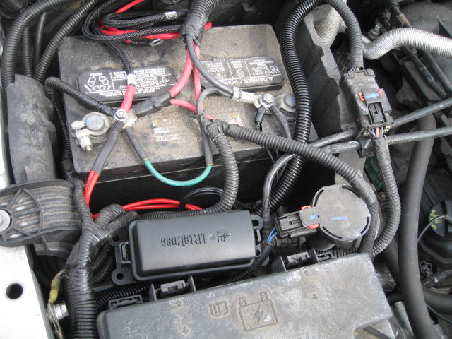
Hear some pics of the finished relay harness. All pics are a little fuzzy.
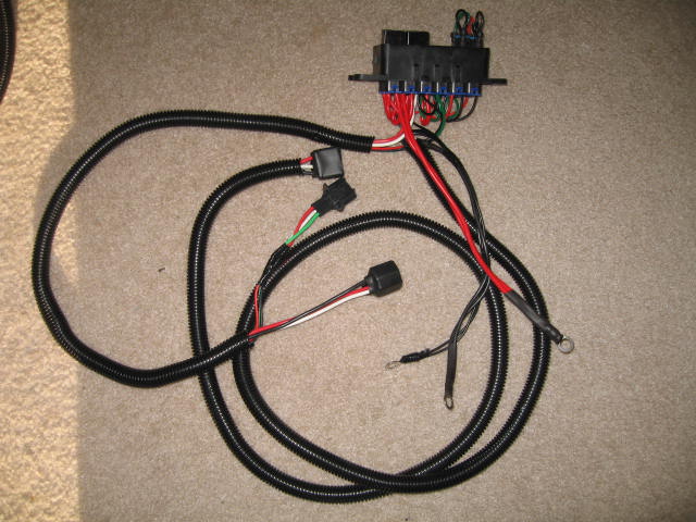
The cap made 2.

Closer pic of the harness with everything mounted.
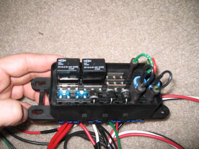
Some of the parts in it.
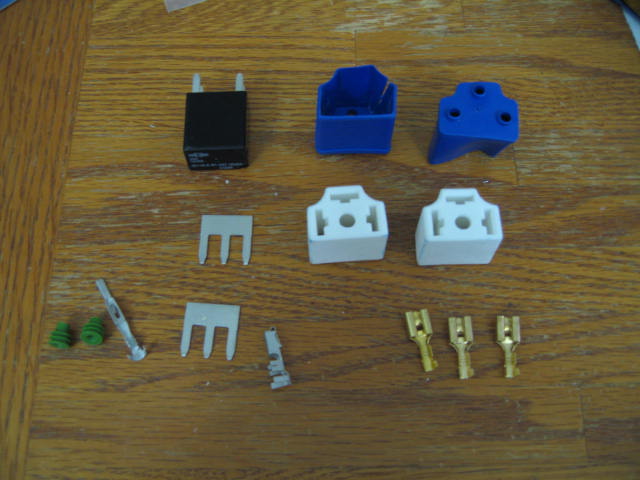
With the cover on.

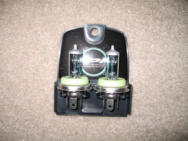
And the bulbs.
Installed
The cap made 2.
Closer pic of the harness with everything mounted.
Some of the parts in it.
With the cover on.
And the bulbs.
Installed
JK Freak
Joined: Oct 2012
Posts: 832
Likes: 1
From: Sabina, OH
Here is a link to my write-up as promised. https://www.jk-forum.com/forums/jk-w...6/#post3509690
Keep in mind that this is not only to fix this problem but I integrated it into my own version of an SPOD. my solution is worked into the schematics (which are tough to see so PM me if you want a better detailed .pdf)
Keep in mind that this is not only to fix this problem but I integrated it into my own version of an SPOD. my solution is worked into the schematics (which are tough to see so PM me if you want a better detailed .pdf)

JK Newbie
Joined: Jun 2014
Posts: 11
Likes: 0
From: Austin, TX
Holy Sh*tballs. I just read through 9 pages of this to realize that I'm going to just install a switch and forget about the high beam relay for my light bar.
Thanks for saving me the time of trying to figure this all out guys!

Thanks for saving me the time of trying to figure this all out guys!