When you click on links to various merchants on this site and make a purchase, this can result in this site earning a commission. Affiliate programs and affiliations include, but are not limited to, the eBay Partner Network.
JK Electrical, Lighting & Sound SystemsBulletin board forum regarding topics such as stereo head units, CD players, MP3 players, speaker systems, amplifiers, hardmounted GPS devices, computers, headlight upgrades, fog lights, off-road lights, general wiring and anti-theft devices.
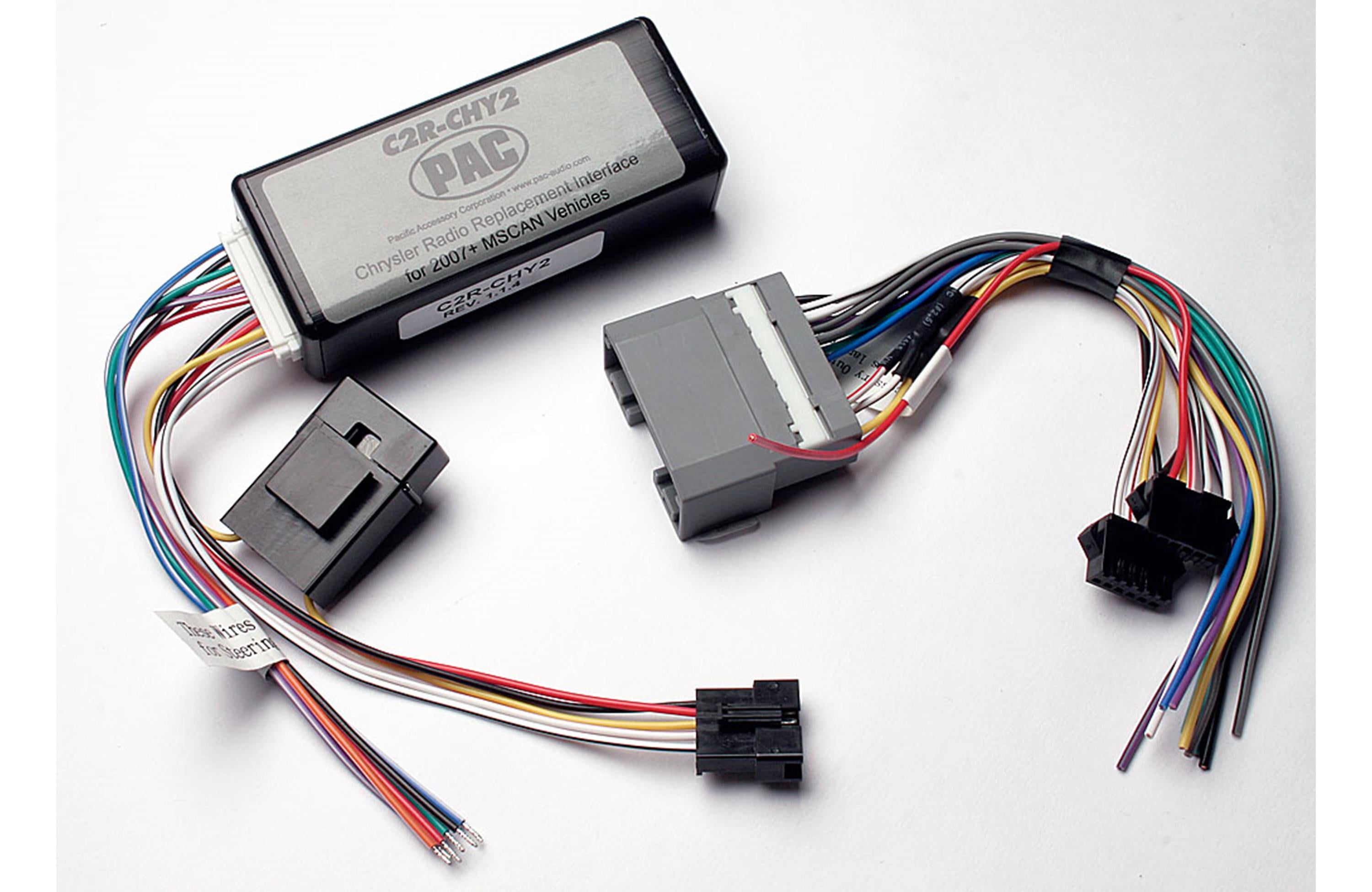
I'm trying to install a Joying radio in my 2007 JK Wrangler and while removing the existing (replacement) radio I cam across this unit:
From what I understand this piece of kit (yes, I said "KIT" didn't I: ) is used to communicate between the replacement radio and the car's CAN bus system, and indeed when I installed my new head unit without it no sound is coming out the speakers. Unfortunately the wiring in the previous head unit was extremely confusing with all manor of wires spliced in with no rhyme or reason and I've been completely unable to work out how to put this piece back in. After a little Internet searching I keep coming across the C2R CHY4 (a later version of this unit) but I'm completely unable to workout how to re-install this one. Does anyone know how I should install it?
Thanks,
Slarti.
Note the 2007 JK does not have steering wheel controls.
Okay, I'm just getting more and more confused by this.
This is the diagram that I thought was going to be the answer to all my questions:
However, after looking at the wiring from the removed unit I took out I see this:
At first glance they seem similar.
That yellow wire in the center comes out of the (constant) +12v port on the 22 pin plug, goes through the connecter to a yellow cable that does indeed run through a fuse and into PIN-9 of the PAC unit.
The colours of the wires entering the PAC unit match the diagram exactly.
That red wire that is meant to connect to the +12V acc line is mysteriously cut short but it is at least in the location expected, and all the input colours entering the connection match the output colours.
The confusing thing though is that according to the diagram the bottom line is meant to go to the red/white line (into PIN-12) and the second bottom is meant to go black/white into PIN-11. The solid red and solid black lines are similarly mismatched. And it's not just upside-down or something as in the diagram the yellow wire is flanked by a black stripe and a solid red, where as the set I removed has the yellow between solid red and striped red.
Note the diagram, although at first glance appears to have the +12v ACC line connecting to the solid red (like mine has), it actually depicts that +12v ACC going into the striped black line.


 ) is used to communicate between the replacement radio and the car's CAN bus system, and indeed when I installed my new head unit without it no sound is coming out the speakers. Unfortunately the wiring in the previous head unit was extremely confusing with all manor of wires spliced in with no rhyme or reason and I've been completely unable to work out how to put this piece back in. After a little Internet searching I keep coming across the C2R CHY4 (a later version of this unit) but I'm completely unable to workout how to re-install this one. Does anyone know how I should install it?