
Looking to rewire rubicon lockers to spod

JK Freak
Joined: Apr 2009
Posts: 775
Likes: 32
From: Colorado
Hmmm, that's a possibilty. You'd have to use two, one for each locker. Maybe you could just release them from the switch harness plug where it attaches to the sPOD PCB and run your leads to the locker grounds.
JK Freak
Joined: Apr 2009
Posts: 775
Likes: 32
From: Colorado
I had an e-mail exchange with him over the weekend and got the same response. He has a point from the liability perspective, as unless you wire in a defeat of some sort there is a risk of inadvertent activation at speed, etc. I asked if they were taking the same position re: using the sPOD to operate ARBs. He responded that the ARB system requires the compressor to be activated before one could accidentally engage one of the lockers.
JK Freak
Joined: Apr 2009
Posts: 775
Likes: 32
From: Colorado
A while back i was thinking about doing the same thing and emailed the sPod guy. He sent me a "theoretical" writing diagram and instructions with the disclaimer it was not advised since it wouldn't prevent accidental activation on pavement (you know gotta please the lawyers, haha). Unfortunately,I don't have the email (or can't find it), but you should be able to just email their customer service for it.

JK Freak
Joined: Jul 2013
Posts: 543
Likes: 2
From: Jersey Shore
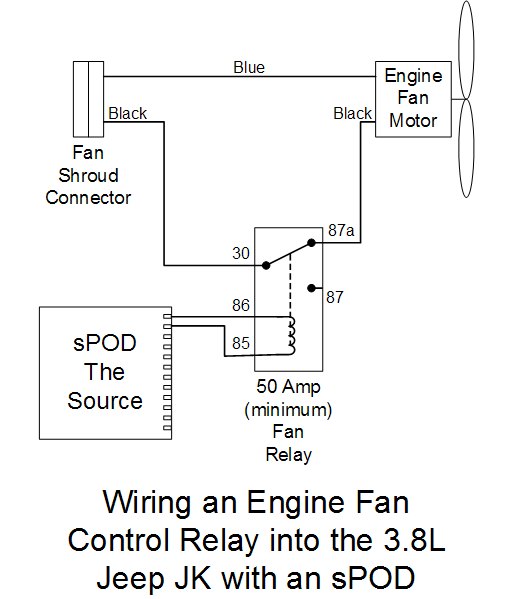
Not sure if this will help, and it would really be a kludge, but maybe what I did to implement an engine fan switch can be modified for this. Here's the diagram for that ...
As for inadvertent actuation of the locker while driving, what I did for that was to modify my dual-lit sPOD (has the button for the switch panel lights) so that the button for the panel lights became an sPOD power button. When pushed off, all of the sPOD switches are inoperative and not backlit. It takes two actions to turn on any of the sPOD-controlled devices: Turn on the power switch, then activate the sPOD toggle for that device. Since all of the sPOD devices I have wired are needed only off-road, this works well for me.
Attachment 589596
Mark, This is perfect example of how to use a relay to actuate anything that is ground enabled. I deal with stuff like this at work all the time. Most of the time I prefer to supply power to a component and control current via a transistor though a NPN transistor to ground.
Thread Starter
JK Freak
Joined: May 2009
Posts: 998
Likes: 1
From: Enumclaw,WA
I had an e-mail exchange with him over the weekend and got the same response. He has a point from the liability perspective, as unless you wire in a defeat of some sort there is a risk of inadvertent activation at speed, etc. I asked if they were taking the same position re: using the sPOD to operate ARBs. He responded that the ARB system requires the compressor to be activated before one could accidentally engage one of the lockers.
Now - I just need a safety mech. Is there a way to ground it sooner in the circuitry so that it still has the same stock limitations? I'd be happy with that at the very least.
JK Freak
Joined: Apr 2009
Posts: 775
Likes: 32
From: Colorado
This is your best option if you want to use the SPOD to actuate them. Its clean and will help to avoid sending unwanted current back into the computer.
Mark, This is perfect example of how to use a relay to actuate anything that is ground enabled. I deal with stuff like this at work all the time. Most of the time I prefer to supply power to a component and control current via a transistor though a NPN transistor to ground.
Mark, This is perfect example of how to use a relay to actuate anything that is ground enabled. I deal with stuff like this at work all the time. Most of the time I prefer to supply power to a component and control current via a transistor though a NPN transistor to ground.
This doesn't solve the bypass's flasing dash locker lights issue. More to ponder.

JK Enthusiast
Joined: Dec 2013
Posts: 103
Likes: 0
From: Hampton VA
Now are you guys currently driving Rubicon's and wanting to re-wire to the sPOD or non-rubi's and wanting to run Rubi axles? I currently drive a 2012 JK and I am swapping in Rubi axles so it should just be simple wiring from the locker to the sPOD. My buddy swapped in Rubi axles into his TJ and ran his wiring straight to the sPOD with no issues at all.
JK Freak
Joined: Apr 2009
Posts: 775
Likes: 32
From: Colorado
That works fine. The complication for Rubis relates to the TCM logic interaction with the locker control. Rubi lockers just switch on & off with relays, but the stuff in between the switch and the relays makes things goofy when just trying to switch with the sPOD.
JK Enthusiast
Joined: May 2013
Posts: 264
Likes: 0
From: Utah
I suppose the real question I'm asking is: Do rubicon lockers operate with 12v power? In theory, I can just hook a car battery to my axle on the bench top and lock it, correct?
JK Junkie

Joined: Feb 2012
Posts: 3,068
Likes: 116
From: Bunnlevel, NC
I don't use an sPod, rather have my own fuse block w/relays that I wired myself. BUT, the below diagrams may help you. Plug 1 (the small plug) is the locker. Plug 2 (larger) is the actuator/indicator.
I don't like the computer controlled locker stuff so I bypassed it completely. One thing missing is that I also wired in a safety switch so that I can't inadvertently activate the lockers, just a small round rocker switch that has to be turned on in order for the OTRATTW switches to get power. So, the small rocker switch feeds 12V positive to spades 2 and 6.
The way I have these wired, the large LED window comes on when I activate the switch, then the small horizontal LED comes on when the lockers actually engage.