Need of a Expert Sponser of LED and Wrangler or Wiring Expert
Subscribe
JK Newbie
Well I just read the other post from where you said to look and as a tech from another field, sometimes you can't help everybody. But it looks like the guy with the issue may have figured it out. If he doesn't, maybe he will listen more maybe he won't.
But I was wondering, in part of one of you posts you said you had stripped your jeep and we're converting to auto accident amongst other things, are you planning on doing good a write up, or can you give some advice on what is needed to complete this install?
Sorry to bug you.
But I was wondering, in part of one of you posts you said you had stripped your jeep and we're converting to auto accident amongst other things, are you planning on doing good a write up, or can you give some advice on what is needed to complete this install?
Sorry to bug you.
Quote:
Sorry to bug you.
Hey ..You are not bothering me...Can I PM ya?Originally Posted by eljeeplv
Well I just read the otherSorry to bug you.

Well, it doesn't look like any experts are going to respond, so I'll share what I have learned about the Center High Mounted Stop Light, or CHMSL.
Review this thread to see that TIPM is made up of several layers of connections. https://www.jk-forum.com/forums/stoc...-study-174919/
The CHIMSL gets power through fuse M1, in the TIPM fuse box.
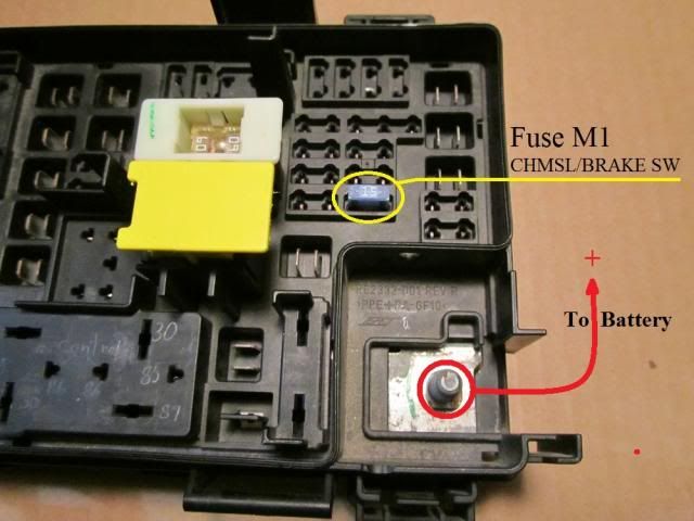
This photo shows fuse M1 is connected directly to the battery on the first layer, known as L1 Bus. The fuses that require unswitched power are on this Bus layer.
12 volts goes through the fuse, and down through all the layers.
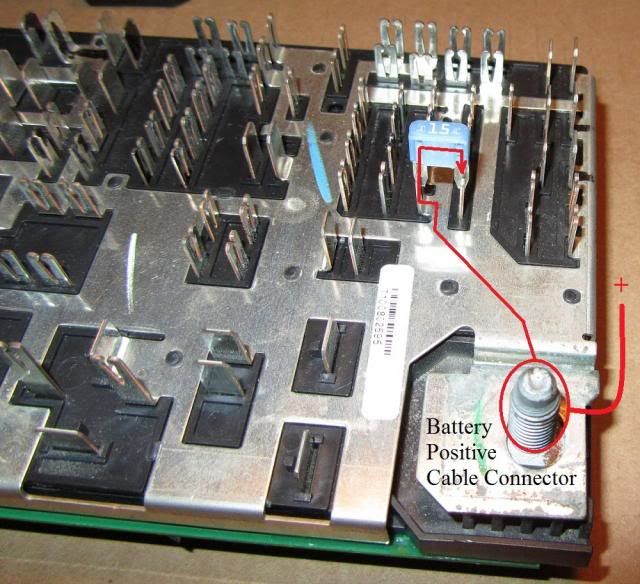
With the Bus layer removed, this photo shows where the 12 volts from fuse M1 is routed on the second layer.
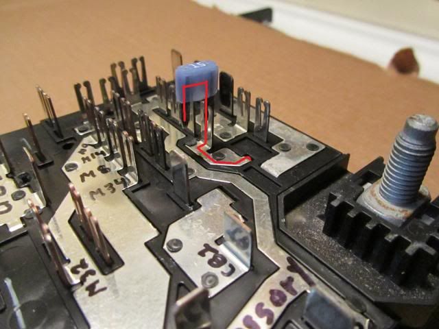
In this photo, you can see the 12 volts leaves fuse M1, and directly exits the TIPM on pin 31, through connector C6, under the TIPM.
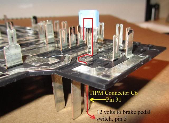
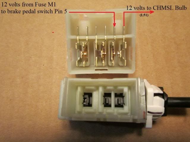
A voltage check with M1 installed, then a continuity check with with M1 removed, and the connector on the pedal mounted brake switch removed, reveals the wire from C6, pin 31, goes directly to pin 5 on the brake switch.
This photo shows how the 12 volts gets through the brake switch, and exits on pin 6.
Continuity checks show the wire from pin 6 goes directly to the CHMSL bulb. This wire does, however, have a tap that goes to the cluster, most likely to trigger the TIPM to turn on the regular stop lights.
Early JK wiring diagrams, and the 2013 JK wiring diagrams all indicate the CHMSL gets power directly from the battery, with no intervention from any computers, CAN Bus, etc. The photos above appear to verify this.
Review this thread to see that TIPM is made up of several layers of connections. https://www.jk-forum.com/forums/stoc...-study-174919/
The CHIMSL gets power through fuse M1, in the TIPM fuse box.
This photo shows fuse M1 is connected directly to the battery on the first layer, known as L1 Bus. The fuses that require unswitched power are on this Bus layer.
12 volts goes through the fuse, and down through all the layers.
With the Bus layer removed, this photo shows where the 12 volts from fuse M1 is routed on the second layer.
In this photo, you can see the 12 volts leaves fuse M1, and directly exits the TIPM on pin 31, through connector C6, under the TIPM.
A voltage check with M1 installed, then a continuity check with with M1 removed, and the connector on the pedal mounted brake switch removed, reveals the wire from C6, pin 31, goes directly to pin 5 on the brake switch.
This photo shows how the 12 volts gets through the brake switch, and exits on pin 6.
Continuity checks show the wire from pin 6 goes directly to the CHMSL bulb. This wire does, however, have a tap that goes to the cluster, most likely to trigger the TIPM to turn on the regular stop lights.
Early JK wiring diagrams, and the 2013 JK wiring diagrams all indicate the CHMSL gets power directly from the battery, with no intervention from any computers, CAN Bus, etc. The photos above appear to verify this.
The diagram is too small for me to view. When I zoom in, I can't read the words.
What does it say under the diagram number?
What does it say under the diagram number?
Quote:
Smes and Have youNames, I was trying to Help a person that was d facts and he isg to be nice. So if your fellow man doesn't step in with different opinions or facts and just sits back and watch the Lost Guy be backed in a corner and not be able to ask others in fear of Upsetting someone, and have them Call him NAMES....that doesn't make a good place to be.Originally Posted by Biggy
Not sure if the OP is right or wrong but I do think it was lame to start this thread in the first place.
[QUOTE=ronjenx;3512014]The diagram is too small for me to view. When I zoom in, I can't read the words.
What does it say under the diagram number?
Sorry, this site's size limited doesn't let you post any bigger...I have to reformat it a few times til it will take it...LOL....yeah that is the New Site....Enter your VIN or models 2010-up...gives everything detail possible and even show you exactly where the Splice/Connector etc is Located
Early JK wiring diagrams, and the 2013 JK wiring diagrams all indicate the CHMSL gets power directly from the battery, with no intervention from any computers, CAN Bus, etc. The photos above appear to verify this.[/QUOTE]
CIRCUIT BOARD (NON-SERVICEABLE) 7 is where all these end up and where Can C+,ect Connect to Battery....
CIRCUIT BOARD (NON-SERVICEABLE) 7 is where all these end up and where Can C+,ect Connect to Battery....