Tapping into reverse +lead?

 01-05-2010, 05:39 PM
#13
JK Enthusiast
Join Date: May 2009
Location: Chicago, IL
Posts: 237
Likes: 0
Received 0 Likes
on
0 Posts
01-05-2010, 06:29 PM
#14
JK Enthusiast
Thread Starter

Join Date: May 2007
Location: dallas texas
Posts: 370
Likes: 0
Received 0 Likes
on
0 Posts
The hce107d
I also can't adjust the clock and calender. The directions tell me to do the p-brake trick so it will let me get to the "video source" but that doesn't seem to be working.
I also can't adjust the clock and calender. The directions tell me to do the p-brake trick so it will let me get to the "video source" but that doesn't seem to be working.
01-06-2010, 03:58 AM
#16
JK Enthusiast
Join Date: May 2009
Location: Chicago, IL
Posts: 237
Likes: 0
Received 0 Likes
on
0 Posts
What is the model of your alpine system? I'll pull the manual and look at it. I just pulled my IVA-W505 manual and believe I found the issue. Orange/White in my manual is not called (Parking Light Output). It is the REVERSE signal input. It is probably the same on yours. If so, you would connect the PAC Green wire (Reverse output) to the Alpine Orange/White (Reverse input). This will automatically trigger the display to turn on the camera when in reverse.
Here's the diagram from my manual.

Where it says + side of reverse lamp is what the PAC device does. When in reverse the PAC device powers the green wire. You can easily test this with a multimeter. Should be zero VDC when the ignition is in the run position and in any gear except reverse. Will be 12VDC when in reverse.
Here's the diagram from my manual.
Where it says + side of reverse lamp is what the PAC device does. When in reverse the PAC device powers the green wire. You can easily test this with a multimeter. Should be zero VDC when the ignition is in the run position and in any gear except reverse. Will be 12VDC when in reverse.
01-06-2010, 06:25 AM
#18
JK Enthusiast
Join Date: May 2009
Location: Chicago, IL
Posts: 237
Likes: 0
Received 0 Likes
on
0 Posts
I pulled the diagrams and annotated them with the connections to the PAC harness.
Diagram 1:
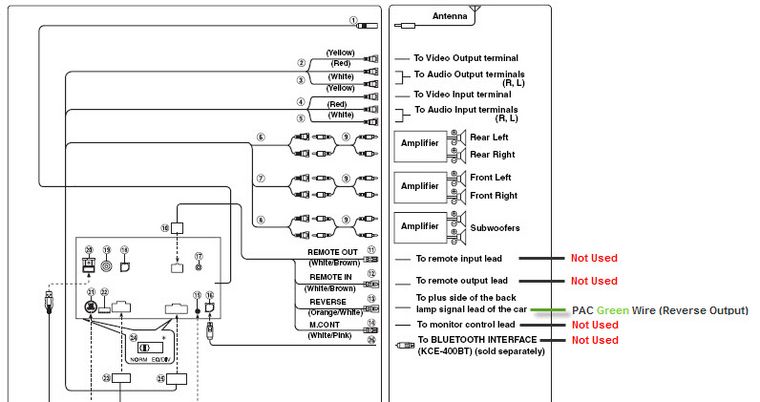
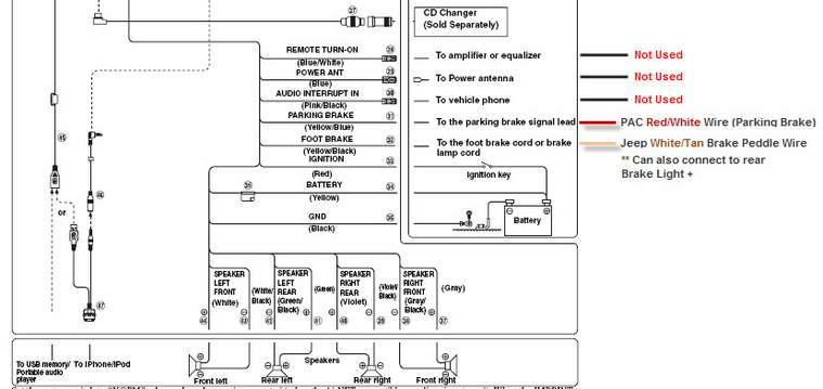
Diagram 2:
PAC Diagram:

You would tie off the PAC Violet/White (VSS); Blue/White (Amp Remote - unless you have one) and the Black/White (not used).
I didn't mark it above, but you connect the composite video output from your camera to the back of your head unit. This is a round RCA connector. Assume you also know that the red Accessory wire coming from the PAC connector goes to the red ignition wire on the Alpine (diagram 2 above). The Yellow wire from the Alpine would connect to a constant 12VDC source (e.g. battery).
Diagram 1:
Diagram 2:
PAC Diagram:
You would tie off the PAC Violet/White (VSS); Blue/White (Amp Remote - unless you have one) and the Black/White (not used).
I didn't mark it above, but you connect the composite video output from your camera to the back of your head unit. This is a round RCA connector. Assume you also know that the red Accessory wire coming from the PAC connector goes to the red ignition wire on the Alpine (diagram 2 above). The Yellow wire from the Alpine would connect to a constant 12VDC source (e.g. battery).
01-06-2010, 06:43 AM
#19
JK Enthusiast
Thread Starter
Join Date: May 2007
Location: dallas texas
Posts: 370
Likes: 0
Received 0 Likes
on
0 Posts
I'm not 100% sure the parking brake and the foot brake are wired correctly then. I will check here at lunch time.
I don't have a RCA type connector coming from my camera. It's just a white pin connector.
I don't have a RCA type connector coming from my camera. It's just a white pin connector.