
Alignment Frustrations - Caster

Thread Starter
JK Enthusiast
Joined: Feb 2009
Posts: 383
Likes: 0
From: Indianapolis, Indiana
Hi Everyone,
I'm on the last stages of the OME LT install. There were a few minor issues; but, nothing that I didn't feel comfortable with, especially with resources like Wayoflife and David at Northridge.
I really want to do everything in my garage, including the alignment. If have read Wayoflife's alignment write-up, and in general it makes good sense.
I do have some frustrations... to the extent that I'm thinking about just taking it in for an alignment. If I can work through the problems, I probably won't go the professional alignment route; but, I want to be comfortable with the driveability.
If anyone can share their thoughts on any of the following issues, I would appreciate it.
I am installing the Currie front upper adjustable control arms which come with the Northridge kit. I adjusted the eye-to-eye distance to match OEM (18-3/4"). I wanted to match the stock control arms so that I could generate data which could be used to make sure that I made the correct adjustments.
I don't believe there are any length measurements provided in any threads for the same kit OME LT kit. If I missed it, and someone can point me to it, I will dial in that length at the beginning.
It seems to be a pretty good rule of thumb to go with 2 degrees greater caster than stock. This sounds like a good place to start, at least.
The following are the issues:
1. When I measure the caster according to Wayoflife's alignment write-up, I have pretty different measurements between right and left. I am measuring across the knuckles. I have used both a magnetic angle finder and a digital level. The results that I get are consistent between the two devices. The right side is at 4 degrees and the left side is at 1 degree. I would like to believe that this variance is caused by the way the knuckles were processed. How can I be sure, though? That is a pretty big variation. How do the alignment shops measure caster?
2. I am struggling, too, to understand how to manipulate the axle to allow me to pull out the bolts that secure the upper control arms to the axle. I have tried using a jack under the pinion, and also under the tie rods. In some cases the bolt is just not coming out. What am I missing? It is pretty tough to know which way the axle needs to be moved if you can't see the actual bolt hole to know which way it is off. I have thought about using a ratchet strap; but, I'm not sure where to tie-off on the axle, and on the frame. Are there other points on the axle housing that I should be using in conjunction with the floor jack? Being that I need to remove and reinstall the axle mount bolts several times during the process, I don't want to damage them by doing it incorrectly.
If this were a trail rig only, I probably wouldn't be so concerned. But, since I will be driving it on the highway, I don't want to compromise.
Thanks for any advice.
Jeff
JK Enthusiast
Joined: Feb 2008
Posts: 365
Likes: 0
From: Gardiner,NY
I installed this lift a few weeks ago and had similar issues. There was a diff. of 1 degree in the stock caster left to right side. With the new currie upper arms I was able to adjust to 6 degrees on both sides. this was almost completely threading in the arms(shorten) I believe the difference in the original caster was caused by the axle mounts and /or axle C's being slightly off when they were welded.You should be able to remove your bolts by using a floor jack to rotate your axle slightly, then use a drift and hammer to tap them out. I bolted up the pumpikin side first because it is a little more difficult to get to.just snug up yours bolts and torque to spec while it is on level ground. 
Thread Starter
JK Enthusiast
Joined: Feb 2009
Posts: 383
Likes: 0
From: Indianapolis, Indiana
Hi Everyone....
I found that I could move the axle by raising the frame opposite the control arm (at least for this case).
Is that a good approach, or should I be working more on the axle itself.
Any thoughts will be appreciated.
Thanks
Jeff
I found that I could move the axle by raising the frame opposite the control arm (at least for this case).
Is that a good approach, or should I be working more on the axle itself.
Any thoughts will be appreciated.
Thanks
Jeff

JK Freak
Joined: Jun 2008
Posts: 655
Likes: 0
From: St. Peters, MO
Since I do not have your lift, but I have one that replaces the lower control arms; I can only tell you how I have been adjusting the caster. Set the axle on a pair of jack stand then putting a jack on the pinion of the pumpkin; you can raise and lower the jack to set the arm lengths. This technique uses the upper arms a pivot point so it might not work since you are replacing the uppers.
I hope this helps.
I hope this helps.
JK Jedi

Joined: Feb 2008
Posts: 7,215
Likes: 10
From: Georgia
There is NO way to measure caster without some form of an alignment machine. Whether it is a manual caster gauge or the latest in laser alignment. No way, no how, no where. Caster is measured in a "arc", and you cannot measure that with a tape measure. All you can do is make both sides equal. Most of the time that is sufficient. Sometimes it's not. The reason caster is measured as an arc is because of SAI, or steering axis inclination. This is an angle built into the chassis and is non adjustable. It is the tilt of the steering axis to the positive side of camber. This helps give caster some good steering returnability coming out of a turn and also helps to give good stability at high speeds.....similar to a good caster setting. Since SAI is not at "zero", this is why it is impossible to measure caster with a tape measure.

JK Jedi Master

Joined: Jan 2008
Posts: 11,463
Likes: 165
From: Austin <--> Colorado Springs
As others have posted, I found that my caster numbers are different on each side. As I looked into it further, I noticed that I was getting up to a full degree of difference depending on which part of the lower 'C' I had the angle finder on.
From the alignment write-up, not mine:
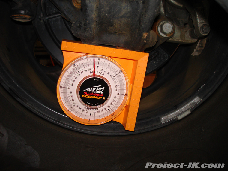
On the edge closest to the middle of the jeep, mine shows 6deg, but closer to the wheel it shows 5deg.
So, I was wondering which would be the more accurate reading?
Also curious about Rednecks post above this one. If I read it right, he's saying that this method does 'not' work and we 'have' to go pay for an alignment to get the right caster? (not a dig on you Redneck, just wanting to make sure I'm understanding what I need to actually do here. )
)
From the alignment write-up, not mine:
On the edge closest to the middle of the jeep, mine shows 6deg, but closer to the wheel it shows 5deg.
So, I was wondering which would be the more accurate reading?
Also curious about Rednecks post above this one. If I read it right, he's saying that this method does 'not' work and we 'have' to go pay for an alignment to get the right caster? (not a dig on you Redneck, just wanting to make sure I'm understanding what I need to actually do here.
)
Trending Topics
JK Jedi Master
Joined: Jan 2008
Posts: 11,463
Likes: 165
From: Austin <--> Colorado Springs
Looking at that pic, if I simply move the Angle Finder back an inch or two toward the tire (still on the C) it shows a lower degree number. I was trying to get a better idea of where exactly on the C gives the most accurate reading.

JK Freak
Joined: Jan 2009
Posts: 722
Likes: 0
From: Carlsbad, CA
chip80 is correct. The vehicle must be perfectly level front to back and side to side to get accurate caster readings. That's why an alignment rack can give the most accurate readings. There may be slight variations in the casting or welding of the axle knuckles but in any case the angle finder must sit flush and level on the metel. Measure the floor surface just below the axle where you are taking the reading to make sure it is at 0 degrees. If it is not, you must compensate for the difference to get an accurate reading.