spod SE source wiring
 09-20-2015, 09:18 PM
#1
JK Enthusiast
Thread Starter

Just wondering exactly what I have to work with here, mostly the switch 1 / 2 signal wire operation. Looking at it I see the screw down points next to the negative terminal, I assume these are the signal wire points mentioned in the specs for that sw1/2 operation, I'm guessing they're also responsible for switch panel lighting?
For something like light bar high beam control, should I be coming out of the spod switch posts to a separate relay and running my signal wire to that?
For something like light bar high beam control, should I be coming out of the spod switch posts to a separate relay and running my signal wire to that?
 09-21-2015, 02:09 AM
#2
JK Junkie
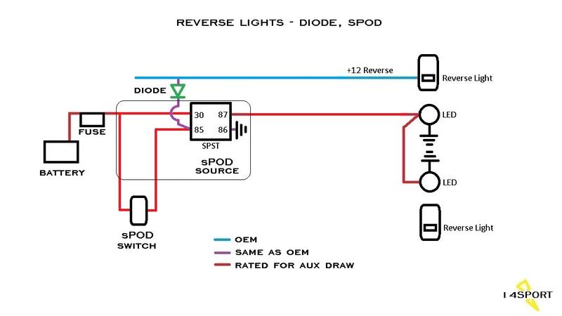
I'm not sure exactly what you are asking (pics may help) but the sPod source already has the relay in it. You would hook up the positive and negative from the light bar directly to the terminals in the source for the switch you want it on. If you also want to trigger it with the high beams, you could tap a high beam wire, add a diode, and connect that wire to the positive side of the control circuit of the relay in the sPod source for the light bar. The diode would prevent backfeeding the high beams when you just want the light bar on. Substitute the high beam wire for the reverse wire in this schematic.
If you don't want to solder in a diode, then you could use a second relay to accomplish the same thing like this...again substituting the high beam wire for reverse wire.
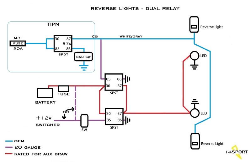
If you don't want to solder in a diode, then you could use a second relay to accomplish the same thing like this...again substituting the high beam wire for reverse wire.
09-23-2015, 03:21 AM
#3
JK Enthusiast
Thread Starter
had a bit of a play around with it today and ended up more puzzled, my priorities have changed slightly as well. regarding the unit itself, I have the 2 connection posts labelled ignition-control. I rigged up a test to the ignition post via a fuse tap off the empty heated seat fuse spot, this acts pretty much as expected, accessory signal is required for power to be granted. the control post I have no idea what it is for? my main concern right now though is that the switch panel lights themsleves are not controlled by the ignition post, so how do I get these to shut off without using the manual push button switch?
09-23-2015, 08:12 AM
#4
JK Junkie
I'm not sure if the se is different than mine or not but the lower LED in the switch pod is fed from the same circuit as the switches so you can't disconnect them in the source and therefore the push button is used to turn the lower LEDs off. Or you could wire them to the dash lights instead which is what I did. I then re-purposed the push button as a lockout for my locker switches to prevent accidental engagement at highway speeds.
Dash lights...https://www.jk-forum.com/forums/jk-e...lights-311176/
Push button...https://www.jk-forum.com/forums/modi...ite-up-324369/
Dash lights...https://www.jk-forum.com/forums/jk-e...lights-311176/
Push button...https://www.jk-forum.com/forums/modi...ite-up-324369/
Last edited by 14Sport; 09-23-2015 at 08:31 AM.
09-23-2015, 08:57 PM
#5
JK Enthusiast
Thread Starter
I'm not sure if the se is different than mine or not but the lower LED in the switch pod is fed from the same circuit as the switches so you can't disconnect them in the source and therefore the push button is used to turn the lower LEDs off. Or you could wire them to the dash lights instead which is what I did. I then re-purposed the push button as a lockout for my locker switches to prevent accidental engagement at highway speeds.
Dash lights...https://www.jk-forum.com/forums/jk-e...lights-311176/
Push button...https://www.jk-forum.com/forums/modi...ite-up-324369/
Dash lights...https://www.jk-forum.com/forums/jk-e...lights-311176/
Push button...https://www.jk-forum.com/forums/modi...ite-up-324369/
As for high beam control, I'm trying to have the light bar come on only when both the switch is in the on position AND high beams are engaged
09-24-2015, 02:16 AM
#6
JK Junkie
 If you are integrating it into the sPod wiring then I would add relay 1 externally and use the sPod for relay 2. Then all you really have to do is change the load feed (pin 30?) of relay 2 from the sPod to the output of relay 1. Just one wire.
Two SPST relays...
Relay 1:
Pin 30 to fused 12V (switched or unswitched depending on your needs)
Pin 85 to high beam wire
Pin 86 to ground
Pin 87 to pin 30 of relay 2.
Relay 2:
Pin 30 to pin 87 of relay 1
Pin 85 to light bar switch (other side of switch to 3A fused 12v switched or unswitched)
Pin 86 to ground
Pin 87 to light bar positive.
The wiring for the load circuit (pin 30 and 87) on both relays should be sized for the light bar draw. Pins 85 and 86 on relay 1 should be sized for the high beam draw. Pins 85 and 86 on relay 2 can be small, like 18 gauge.
Basically what that is doing is interrupting the power feed to the light bar with relay 1 inserted. Relay 1 will only pass power to relay 2 if the high beams are on so the switch to the light bar will only work when the high beams are on. As a result, leaving the switch in the on position will make the light bar come on every time you hit the high beams, a selectable "light bar on with high beams" switch if you will. That's what I believe you are looking for rather than having the light bar independent?
Last edited by 14Sport; 09-24-2015 at 02:32 AM.
09-24-2015, 06:09 PM
#7
JK Enthusiast
Thread Starter
Yep exactly what I'm looking for, but the SE might be a challenge to work with, the relays on that appear to be little ICs. There are some holes, but I'm not sure what they're for. 8 Circuit SE System (switch panel version) for Jeep JK 2009-2015
I may have to come out from a source positive terminal to the 2nd relay, guessing like this:
pin 30 source pos
pin 85 to high beam wire
pin 86 ground
pin 87 light bar pos
I think this should work? But does pin 85 actually draw anything? I was just going to run a fuse tap using 18 gauge for the high beam signal wire, any issues?
Trending Topics
09-25-2015, 09:53 AM
#8
JK Junkie
Yep exactly what I'm looking for, but the SE might be a challenge to work with, the relays on that appear to be little ICs. There are some holes, but I'm not sure what they're for. 8 Circuit SE System (switch panel version) for Jeep JK 2009-2015
I may have to come out from a source positive terminal to the 2nd relay, guessing like this:
pin 30 source pos
pin 85 to high beam wire
pin 86 ground
pin 87 light bar pos
I think this should work? But does pin 85 actually draw anything? I was just going to run a fuse tap using 18 gauge for the high beam signal wire, any issues?
I may have to come out from a source positive terminal to the 2nd relay, guessing like this:
pin 30 source pos
pin 85 to high beam wire
pin 86 ground
pin 87 light bar pos
I think this should work? But does pin 85 actually draw anything? I was just going to run a fuse tap using 18 gauge for the high beam signal wire, any issues?
Yeah using the sPod for relay 1 makes more sense. That should work. The second relay will power every time the high beams are on but won't have any load feed unless the switch is on.

As always, I recommend running the wires externally to verify before final install.
Last edited by 14Sport; 09-26-2015 at 02:30 AM.
09-27-2015, 06:05 PM
#9
JK Enthusiast
Thread Starter
Pin 85 draws milliamps. The wire gauge should match the OEM wire you tap. If you use a smaller gauge then I would stick a 3A fuse on it.
Yeah using the sPod for relay 1 makes more sense. That should work. The second relay will power every time the high beams are on but won't have any load feed unless the switch is on.
As always, I recommend running the wires externally to verify before final install.
Yeah using the sPod for relay 1 makes more sense. That should work. The second relay will power every time the high beams are on but won't have any load feed unless the switch is on.
As always, I recommend running the wires externally to verify before final install.