Notices
JK Electrical, Lighting & Sound Systems Bulletin board forum regarding topics such as stereo head units, CD players, MP3 players, speaker systems, amplifiers, hardmounted GPS devices, computers, headlight upgrades, fog lights, off-road lights, general wiring and anti-theft devices.

Switchable Aux Reverse Lights - Schematic Feedback Requested

Thread Tools
 
Old Feb 7, 2015 | 04:09 AM
  #41  
dewey7015's Avatar
JK Newbie
 
Joined: Nov 2013
Posts: 99
Likes: 1
From: cape cod, MA
Default

Originally Posted by 14Sport
I recommended mounting in the rear because of what I was told about the reverse wire not being 12v in the tub. But in the side note in my earlier post, I found out that isn't true so I would mount the relays under the hood. Then you only need to run 1 wire to the back.

To post pics, don't use the quick reply. You have to be in the advanced editor and you will see Manage Attachments near the bottom. When you click that a dialogue box will open. Click add files then select files. Click on the files from your computer that you want and then click open and then upload files and then done.
My wiring is experience is just ok. planning out circuits is a much higher level than where I am...
I don't want to hijack this thread with teaching me how to post pics...basically, I think people are taking cell phone pics when writing something up. do they do the whole write up from their phone?? same problem when posting a pic on craigslist. 1 take pic on phone. 2 email it to myself. 3 use laptop to try and find photo, and post to craigslist. 4 seems like a lot of work.
5 basal joint in the (base) of the thumb is the #1 joint to wear out in the hand. see? learned something there...
Reply
Old Feb 7, 2015 | 05:31 AM
  #42  
14Sport's Avatar
Thread Starter
JK Junkie
 
Joined: Nov 2013
Posts: 3,703
Likes: 8
From: The Dirty South
Default


I don't use my phone for posting. I take the pics with a camera and then put them on my hard drive.
Reply
Old Feb 7, 2015 | 05:36 AM
  #43  
14Sport's Avatar
Thread Starter
JK Junkie
 
Joined: Nov 2013
Posts: 3,703
Likes: 8
From: The Dirty South
Default

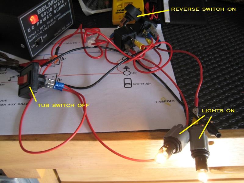
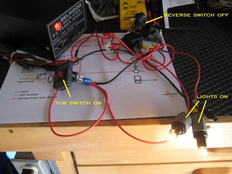
Okay so I bench tested the schematic and everything worked as planned. Sorry for the lights I used that was all I had lying around but they did the trick. They're JK fender marker lights. I used a second switch to simulate power coming through the reverse wire.


Attached Thumbnails Click image for larger version

Name:	ReverseDualRelay 001 (Medium).jpg
Views:	1400
Size:	70.9 KB
ID:	595680   Click image for larger version

Name:	ReverseDualRelay 002 (Medium).jpg
Views:	1398
Size:	66.3 KB
ID:	595681   Click image for larger version

Name:	ReverseDualRelay 003 (Medium).jpg
Views:	1392
Size:	64.6 KB
ID:	595682   Click image for larger version

Name:	ReverseDualRelay 004 (Medium).jpg
Views:	1380
Size:	74.3 KB
ID:	595683  

Last edited by 14Sport; Feb 7, 2015 at 05:44 AM.
Reply
Old Feb 7, 2015 | 06:12 AM
  #44  
14Sport's Avatar
Thread Starter
JK Junkie
 
Joined: Nov 2013
Posts: 3,703
Likes: 8
From: The Dirty South
Default

Thought of another test I should have run.

Added LED strip to simulate OEM reverse lights to show no backfeeding.


Attached Thumbnails Click image for larger version

Name:	ReverseDualRelay 005 (Medium).jpg
Views:	1370
Size:	68.0 KB
ID:	595690   Click image for larger version

Name:	ReverseDualRelay 006 (Medium).jpg
Views:	1313
Size:	74.7 KB
ID:	595691  
Reply
Old Feb 7, 2015 | 06:18 AM
  #45  
pickjones's Avatar
JK Freak
 
Joined: Apr 2009
Posts: 579
Likes: 1
From: Westchester, NY
Default

Originally Posted by 14Sport
Thought of another test I should have run.

Added LED strip to simulate OEM reverse lights to show no backfeeding.
You're a hero!
Reply
Old Feb 7, 2015 | 06:25 AM
  #46  
14Sport's Avatar
Thread Starter
JK Junkie
 
Joined: Nov 2013
Posts: 3,703
Likes: 8
From: The Dirty South
Default

Originally Posted by pickjones
You're a hero!
Lol...I ran that last test for you.
Reply
Old Feb 7, 2015 | 06:51 AM
  #47  
smittycm's Avatar
JK Freak
Veteran: Marine Corp
 
Joined: Dec 2011
Posts: 586
Likes: 1
From: Okinawa, Japan
Default

Originally Posted by 14Sport
Thought of another test I should have run.

Added LED strip to simulate OEM reverse lights to show no backfeeding.
Nice work! Good to know I won't be running the wiring for nothing. Thanks again for the work on this.
Reply
Old Feb 7, 2015 | 07:00 AM
  #48  
14Sport's Avatar
Thread Starter
JK Junkie
 
Joined: Nov 2013
Posts: 3,703
Likes: 8
From: The Dirty South
Default

Originally Posted by smittycm
Nice work! Good to know I won't be running the wiring for nothing. Thanks again for the work on this.
No problem. Still looking for real world confirmation though.

Last edited by 14Sport; Feb 7, 2015 at 07:05 AM.
Reply
Old Feb 7, 2015 | 07:24 AM
  #49  
pickjones's Avatar
JK Freak
 
Joined: Apr 2009
Posts: 579
Likes: 1
From: Westchester, NY
Default

Originally Posted by 14Sport
Thought of another test I should have run.

Added LED strip to simulate OEM reverse lights to show no backfeeding.
Originally Posted by pickjones

You're a hero!
Well I just tested this out and for me, hitting the switch does back feed the oem lights. Boooo. Only thing I can come up with is that relays must function differently.
Reply
Old Feb 7, 2015 | 07:40 AM
  #50  
14Sport's Avatar
Thread Starter
JK Junkie
 
Joined: Nov 2013
Posts: 3,703
Likes: 8
From: The Dirty South
Default

Originally Posted by pickjones
Well I just tested this out and for me, hitting the switch does back feed the oem lights. Boooo. Only thing I can come up with is that relays must function differently.
You sure you have the oem reverse wire attached to pin 85 with 86 to ground? Nothing else should be connected to these pins. Make sure you didn't run a jumper wire between the aux light and the reverse light at the tail light.

If the wiring is correct, then test the relay. With a continuity tester check across pins 85 an 86. It should show continuity. Check across pins 85 and 87. Should show open line. Same as across 85 and 30. Then check across pins 30 and 87. Should show open line. Then apply 12v to pin 85 with pin 86 to ground. Check across pins 30 and 87 again. This time it should show continuity.

Last edited by 14Sport; Feb 7, 2015 at 08:16 AM.
Reply


All times are GMT -8. The time now is 01:17 AM.