Brandmotion- Jeep Wrangler Adjustable Rear Vision Camera 2007- Present
 04-17-2016, 03:16 PM
#1
Super Moderator

Thread Starter
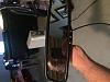
So have you ever been in the parking lot at the mall and realize with the bigger tires sitting on your tire carrier you just cannot see if that Renegade behind you is going to get personal with your tire? Or how about when you are trying to back up on the trail and need that little extra couple of inches to get out of a tight spot or better yet if you are going slide down the rock you just spent 5 minutes getting up. Well last week I received my Brandmotion Rear Vision Camera
Installation was pretty straight-forward. Yes read the directions on how this goes together. Disclaimer: I read the instruction, however final installation, I did not use the supplied mount due to the wheels that I have and will cover my work around.
Tools required:
Diagonal Cutters
Wire strippers and crimps
Spare tire removal tools
#20 Torque Tip for the mirror
Hand full of Zip Ties
1 End crimps
1 wire connector
Ease of Installation: Basic knowledge of your Jeep and where to get 12 VDC.
First and foremost is to estimate how long this is going to take and add 3 hours. Why because when the wife starts asking how long you can give an estimate over the required time so that she will leave you alone. Also if you start at 4:00 pm thinking it will take a couple of hours and 4 hours later it is dark and you are fighting with the stinking flashlight to light up the area you are working you can only cuss at yourself for taking so long. Ok you can all smile now because you have done that.
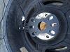
After removing the spare tire from the carrier I used two saw horses as a work bench because picking up a 35 mounted on a ATX Slap is not fun. With the tire laying face down I aligned the supplied mount with camera attached on the stud holes to see how the camera will fit. After maneuvering the mount around and making adjustments I determined that supplied mount will not work with my wheels.
So it was to plan B, how to make it work.
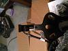
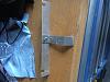
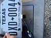
With having relocated my license plate to the center of my spare tire I chose to fabricate a license plate mount. I had some strips of aircraft aluminum laying around from a project that I was going to do but did not so it was what I used. You can pick up aluminum stock at Home Depot or Lowe�s. After measuring the distance between the license plate lower mounting bolts (length) I added an inch, giving me � inch on either side. Laying the strip of aluminum on one side of the bolts and align with the bottom of the license plate and mark. The lay the strip of aluminum on top of the license plate and mark the center of each fastener. This will be your guide to where you will drill your holes. I chose to make a key way so that my camera mount will slide between the plate and mount because I have LED lights lighting the plate. Place the aluminum strip on a 2x4 and secure with clamps. Using a center punch mark the holes where to drill. BECAREFUL NOT TO DRILL TOO FAST BECAUSE THE ALUMINUM WILL CATCH THE BIT AND SPIN IF YOU ARE NOT CAREFUL. Then with a cut off wheel on the Dremel I cut a slot for the bracket to slide up and secured the license plate back to the mount.
With a 1/8 drill bit I drilled the hole to mount the camera onto the bracket but did not mount camera at this time.
Note: If you have not bent aluminum before there are some particulars things to know. Aluminum can be bent using two pieces of wood and a non-marring hammer or a bench top vice. Also be sure to check for the grain and bend against the grain not with, because you can cause fatigue and cracking. I have a butcher-block workbench that used along with a 2x4. Place the aluminum in your securing device and make the first bend to 90*, this is where the non-marring hammer helps get the angle just right. With the 90* bend in place swap ends and bend the opposite direction of the 90* to about 30*-45*. Again I used the supplied mount to achieve the correct angle.
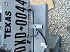
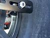
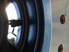
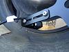
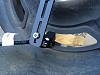
Once the mount is installed I removed then routed the camera through the slots in the ATX Slab wheels and secured the camera to the bracket using a small Phillips screwdriver and � wrench.
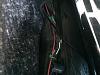
Now comes the fun part of routing the wires. Since I have the LoD Gen III tire carrier I chose to route the wire harness along the existing wires for the license plate lights. Additionally since I have the EVO Trail Table I loosened the top bolts enough to get the cable behind it. Prior to moving forward I put plastic wire loom on the exposed section to one protect against the elements but also to eliminate the chance of the wires chaffing.
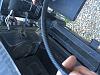
Using supplied zip ties I secured the cable to the CB Coax and license plate lighting. After removing the factory sub woofer I routed the cable along the body under the factory carpet along the passenger side of the Jeep pushing it under the plastic.
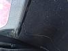
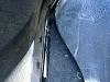
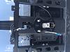
Once the wires have been routed to the passenger side of the Jeep remove the glove box so that you can gain access to the empty area behind it. Feed the wires up from the bottom of the passenger dash and through the glove box opening.
Remove old review mirror suing a #20 Torque bit and reuse the screw to secure new mirror. With the wires since I have a sport cage I chose to route them along the top of the cage with my CB wires and coax following the path the CB wires took to behind the dash.
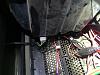
This can be tricky if you have a sport cage, just be patient and if you have little hands you will do better than this guy with ham hands. Any way the wires are now coming out of the glove box with the camera wires. This is where I waivered from the instructions. I have a DIY relay system with an open switch where I chose to get my 12V to power both the camera and the mirror. NOTE: The instructions state to use the 12v power outlet on the lower right side of the dash. After connecting both power wires for the mirror and camera I used an in line splice. Then I connected the round wires together with a common ground using and end splice. Now that power is available it is time to op check. Turned the switch on and the camera and mirror has power. With both the camera and mirror on it is time to fine-tune the position of the camera.
Overall a fairly easy install just time consuming. I did not realize just how much I would use it. Not that it is installed I have used it several times and will continue to use it.
Cheers,
Will
Installation was pretty straight-forward. Yes read the directions on how this goes together. Disclaimer: I read the instruction, however final installation, I did not use the supplied mount due to the wheels that I have and will cover my work around.
Tools required:
Diagonal Cutters
Wire strippers and crimps
Spare tire removal tools
#20 Torque Tip for the mirror
Hand full of Zip Ties
1 End crimps
1 wire connector
Ease of Installation: Basic knowledge of your Jeep and where to get 12 VDC.
First and foremost is to estimate how long this is going to take and add 3 hours. Why because when the wife starts asking how long you can give an estimate over the required time so that she will leave you alone. Also if you start at 4:00 pm thinking it will take a couple of hours and 4 hours later it is dark and you are fighting with the stinking flashlight to light up the area you are working you can only cuss at yourself for taking so long. Ok you can all smile now because you have done that.
After removing the spare tire from the carrier I used two saw horses as a work bench because picking up a 35 mounted on a ATX Slap is not fun. With the tire laying face down I aligned the supplied mount with camera attached on the stud holes to see how the camera will fit. After maneuvering the mount around and making adjustments I determined that supplied mount will not work with my wheels.
So it was to plan B, how to make it work.
With having relocated my license plate to the center of my spare tire I chose to fabricate a license plate mount. I had some strips of aircraft aluminum laying around from a project that I was going to do but did not so it was what I used. You can pick up aluminum stock at Home Depot or Lowe�s. After measuring the distance between the license plate lower mounting bolts (length) I added an inch, giving me � inch on either side. Laying the strip of aluminum on one side of the bolts and align with the bottom of the license plate and mark. The lay the strip of aluminum on top of the license plate and mark the center of each fastener. This will be your guide to where you will drill your holes. I chose to make a key way so that my camera mount will slide between the plate and mount because I have LED lights lighting the plate. Place the aluminum strip on a 2x4 and secure with clamps. Using a center punch mark the holes where to drill. BECAREFUL NOT TO DRILL TOO FAST BECAUSE THE ALUMINUM WILL CATCH THE BIT AND SPIN IF YOU ARE NOT CAREFUL. Then with a cut off wheel on the Dremel I cut a slot for the bracket to slide up and secured the license plate back to the mount.
With a 1/8 drill bit I drilled the hole to mount the camera onto the bracket but did not mount camera at this time.
Note: If you have not bent aluminum before there are some particulars things to know. Aluminum can be bent using two pieces of wood and a non-marring hammer or a bench top vice. Also be sure to check for the grain and bend against the grain not with, because you can cause fatigue and cracking. I have a butcher-block workbench that used along with a 2x4. Place the aluminum in your securing device and make the first bend to 90*, this is where the non-marring hammer helps get the angle just right. With the 90* bend in place swap ends and bend the opposite direction of the 90* to about 30*-45*. Again I used the supplied mount to achieve the correct angle.
Once the mount is installed I removed then routed the camera through the slots in the ATX Slab wheels and secured the camera to the bracket using a small Phillips screwdriver and � wrench.
Now comes the fun part of routing the wires. Since I have the LoD Gen III tire carrier I chose to route the wire harness along the existing wires for the license plate lights. Additionally since I have the EVO Trail Table I loosened the top bolts enough to get the cable behind it. Prior to moving forward I put plastic wire loom on the exposed section to one protect against the elements but also to eliminate the chance of the wires chaffing.
Using supplied zip ties I secured the cable to the CB Coax and license plate lighting. After removing the factory sub woofer I routed the cable along the body under the factory carpet along the passenger side of the Jeep pushing it under the plastic.
Once the wires have been routed to the passenger side of the Jeep remove the glove box so that you can gain access to the empty area behind it. Feed the wires up from the bottom of the passenger dash and through the glove box opening.
Remove old review mirror suing a #20 Torque bit and reuse the screw to secure new mirror. With the wires since I have a sport cage I chose to route them along the top of the cage with my CB wires and coax following the path the CB wires took to behind the dash.
This can be tricky if you have a sport cage, just be patient and if you have little hands you will do better than this guy with ham hands. Any way the wires are now coming out of the glove box with the camera wires. This is where I waivered from the instructions. I have a DIY relay system with an open switch where I chose to get my 12V to power both the camera and the mirror. NOTE: The instructions state to use the 12v power outlet on the lower right side of the dash. After connecting both power wires for the mirror and camera I used an in line splice. Then I connected the round wires together with a common ground using and end splice. Now that power is available it is time to op check. Turned the switch on and the camera and mirror has power. With both the camera and mirror on it is time to fine-tune the position of the camera.
Overall a fairly easy install just time consuming. I did not realize just how much I would use it. Not that it is installed I have used it several times and will continue to use it.
Cheers,
Will

