DIY Fuse and Relay Box
 03-23-2014, 03:35 PM
#1
JK Newbie
Thread Starter
How To Build A Fuse/Relay Box
This is a very simple way to clean up all that mess of wires and randomly placed relays under the hood of your vehicle. I made mine for my 2014 Jeep Wrangler Unlimited, but you could use this for any vehicle where space permits. With this design, I wanted to make sure that I had enough components in it to allow for expansion as I decide to add things to my Jeep, but if you know you will only have a need for X number of relays, then this device could be even smaller, or bigger. This project is not a difficult one at all, though it can be time consuming but is well worth it when you consider the money savings compared to commercial products. Keep in mind that this is a DIY project and although it has worked extremely well for me and is perfectly safe when put together correctly, I am not liable or responsible for any malfunctions, catastrophic failures, or damages to your vehicle.

Parts list:
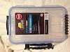
A. 1 waterproof storage box of some sort. I used a medium size Plano waterproof stowaway box. Space was tight, but it worked perfectly for the internals. This one had dividers inside that I had to cut out using a dremel tool.
B. However many relays you plan to use, for my purposes I used 5 40amp SPST automotive relays and 2 40amp dual output relays from KC
C. A Bussman Fuse panel. I got the first one off of Amazon.com, The second I got from Auto Zone. If you choose to only use the one from Auto Zone, you will need to get something to connect your grounds to.
D. One 50amp automatic reset circuit breaker
I got mine from Amazon.com.
E. Fuses, I used 30amp fuses.
F. Wire. I used 10 gauge wire for the main power wire and main ground (yellow for power, black for ground). I used green 16 gauge wire to connect the relays to the switches, 14 gauge red wire for the relay power out and relay power in, and 14 gauge black wire for the relay grounds.
G. Lots, and lots of 16-14 gauge spade connectors (blue). Depending on how many relays you will have the amount of spade connectors will vary. SPST relays will need four each, plus 2 more to connect each relay to the ground and fuse panel. In my case I used 46 spade connectors.
H. 1 package of 12-10 gauge ring terminals (yellow). I used 8 total.
I. 16-14 gauge bullet connectors (blue). This again varies depending on how many relays you use, these will connect the relay power out and switch power wires to the wires you run in your vehicle. You can also use butt connectors but I wanted the option to quickly disconnect or connect at any time. I used 16.
Tools Needed:
Wire cutters/strippers/crimpers, electrical tape in various colors, zip ties (small and in at least 2 colors), super glue (I used Gorilla brand Gel), automotive silicon sealant, dremel tool or sharp knife/razor blade. Electrical conduit and heat shrink, if desired. You can also use spray paint on the box if you like, if you do I would suggest using a high temp paint since it will be in the engine compartment.
Step One
For this step we will remove the dividers in our waterproof stowaway box using the dremel tool or a sharp knife.
Step Two
Now start super gluing the fuse panel ends together if you used two, also glue your circuit breaker in position and wire it to the fuse panel when dry with the yellow 10 gauge wire and ring terminals. Now glue your relays together, this will make wiring them all much easier and will be easier to keep track of. You will want all of your relays to be glued so that all the grounds are on one side. The ground pin is #85.
This is a very simple way to clean up all that mess of wires and randomly placed relays under the hood of your vehicle. I made mine for my 2014 Jeep Wrangler Unlimited, but you could use this for any vehicle where space permits. With this design, I wanted to make sure that I had enough components in it to allow for expansion as I decide to add things to my Jeep, but if you know you will only have a need for X number of relays, then this device could be even smaller, or bigger. This project is not a difficult one at all, though it can be time consuming but is well worth it when you consider the money savings compared to commercial products. Keep in mind that this is a DIY project and although it has worked extremely well for me and is perfectly safe when put together correctly, I am not liable or responsible for any malfunctions, catastrophic failures, or damages to your vehicle.
Parts list:
A. 1 waterproof storage box of some sort. I used a medium size Plano waterproof stowaway box. Space was tight, but it worked perfectly for the internals. This one had dividers inside that I had to cut out using a dremel tool.
B. However many relays you plan to use, for my purposes I used 5 40amp SPST automotive relays and 2 40amp dual output relays from KC
C. A Bussman Fuse panel. I got the first one off of Amazon.com, The second I got from Auto Zone. If you choose to only use the one from Auto Zone, you will need to get something to connect your grounds to.
D. One 50amp automatic reset circuit breaker
I got mine from Amazon.com.
E. Fuses, I used 30amp fuses.
F. Wire. I used 10 gauge wire for the main power wire and main ground (yellow for power, black for ground). I used green 16 gauge wire to connect the relays to the switches, 14 gauge red wire for the relay power out and relay power in, and 14 gauge black wire for the relay grounds.
G. Lots, and lots of 16-14 gauge spade connectors (blue). Depending on how many relays you will have the amount of spade connectors will vary. SPST relays will need four each, plus 2 more to connect each relay to the ground and fuse panel. In my case I used 46 spade connectors.
H. 1 package of 12-10 gauge ring terminals (yellow). I used 8 total.
I. 16-14 gauge bullet connectors (blue). This again varies depending on how many relays you use, these will connect the relay power out and switch power wires to the wires you run in your vehicle. You can also use butt connectors but I wanted the option to quickly disconnect or connect at any time. I used 16.
Tools Needed:
Wire cutters/strippers/crimpers, electrical tape in various colors, zip ties (small and in at least 2 colors), super glue (I used Gorilla brand Gel), automotive silicon sealant, dremel tool or sharp knife/razor blade. Electrical conduit and heat shrink, if desired. You can also use spray paint on the box if you like, if you do I would suggest using a high temp paint since it will be in the engine compartment.
Step One
For this step we will remove the dividers in our waterproof stowaway box using the dremel tool or a sharp knife.
Step Two
Now start super gluing the fuse panel ends together if you used two, also glue your circuit breaker in position and wire it to the fuse panel when dry with the yellow 10 gauge wire and ring terminals. Now glue your relays together, this will make wiring them all much easier and will be easier to keep track of. You will want all of your relays to be glued so that all the grounds are on one side. The ground pin is #85.

The following users liked this post:
huesos350 (02-13-2018)
03-23-2014, 03:42 PM
#2
JK Newbie
Thread Starter
Step Three
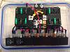
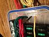
Start your wiring. Using the blue spade connectors begin wiring all of the same pin in your relays using the colored 14 gauge wire. I put the #85 ground pin at the bottom and began by wiring all of the ground pins to the ground panel on the fuse panel. Because space if limited and we are trying to keep the project both small and cost effective, plan your wiring accordingly doing your best to use the least amount of wire necessary.
Step Four
Continue Wiring. Now that you have all of your #85 ground pins wired, begin wiring all of the #30 relay power IN pins to the fuse panel using the red 14 gauge wire and blue spade connectors. Again, preplan your wiring to use the least amount of wire needed to complete the job.
Step Five
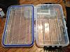
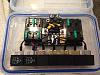
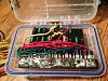
At this point you should have both the #85 and #30 pins completely wired to the fuse panels. Now, keeping the fuse panel in place, mark the location for the 4 holes that will be needed to run the wires out of the stowaway box. Use one hole for the power OUT wires, one hole for the SWITCH power wires, one hole for the direct power wire from the battery, and one for the main ground wire. Start by drilling or cutting a small hole, and carefully increase the hole size to fit each wires. The tighter the fit, the better seal everything will make keeping your relay box watertight and protected from the elements. If you decide to do it exactly as I have with 2 dual output relays, I suggest making a separate hole specifically for those power OUT wires so they are easy to keep separated from the standard SPST relays. Pictured to the right is what it will look like at completion of the project but before sealing.
Step Six
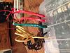
Continue wiring. Now we can wire the relay power OUT wires. start by cutting 1� to 1.5� sections of the red 14 gauge wire for each relay, then connect a blue spade connector to one end. As you connect these wires to the #87 relay power OUT pins run the tail endif the wire though the holes you drilled in the last step. Once each wire end is outside the box, you will want to mark them in some way to keep track of which wire goes to which relay and which switch controls it. My method was to number the relays 1 to 7 from left to right, and I used colored zip ties on the wires to keep track of that. Seems difficult but makes sense, I used black zip ties to equal 1, and white zip ties to equal 2. So if I have a wire with 2 white zip ties and one black zip tie, that wire is for the #5 relay (2+2+1=5).
Step Seven
Continue wiring. At the point the #85, #30, and #87 pins should all be wired completely with the relay power out wires running to the outside of the stowaway box. Now you can wire the number #86 SWITCH power pins. Using the same method in STEP SIX, cut green 14 gauge wire in 1� to 1.5� sections, attach to the #86 pins, run to the outside of the stowaway box, and mark them with zip ties that correlate to the number relay.
Step Eight
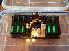
Now wire yellow 10 gauge DIRECT POWER wire to the circuit breaker using the yellow ring terminals. Then wire the black 10 gauge MAIN GROUND wire to the ground panel on the fuse block using the yellow ring terminals. Run both wires out of the stowaway box leaving more than enough wire to connect them to the battery and suitable ground once installed in your vehicle. Your project should now look the this:
Start your wiring. Using the blue spade connectors begin wiring all of the same pin in your relays using the colored 14 gauge wire. I put the #85 ground pin at the bottom and began by wiring all of the ground pins to the ground panel on the fuse panel. Because space if limited and we are trying to keep the project both small and cost effective, plan your wiring accordingly doing your best to use the least amount of wire necessary.
Step Four
Continue Wiring. Now that you have all of your #85 ground pins wired, begin wiring all of the #30 relay power IN pins to the fuse panel using the red 14 gauge wire and blue spade connectors. Again, preplan your wiring to use the least amount of wire needed to complete the job.
Step Five
At this point you should have both the #85 and #30 pins completely wired to the fuse panels. Now, keeping the fuse panel in place, mark the location for the 4 holes that will be needed to run the wires out of the stowaway box. Use one hole for the power OUT wires, one hole for the SWITCH power wires, one hole for the direct power wire from the battery, and one for the main ground wire. Start by drilling or cutting a small hole, and carefully increase the hole size to fit each wires. The tighter the fit, the better seal everything will make keeping your relay box watertight and protected from the elements. If you decide to do it exactly as I have with 2 dual output relays, I suggest making a separate hole specifically for those power OUT wires so they are easy to keep separated from the standard SPST relays. Pictured to the right is what it will look like at completion of the project but before sealing.
Step Six
Continue wiring. Now we can wire the relay power OUT wires. start by cutting 1� to 1.5� sections of the red 14 gauge wire for each relay, then connect a blue spade connector to one end. As you connect these wires to the #87 relay power OUT pins run the tail endif the wire though the holes you drilled in the last step. Once each wire end is outside the box, you will want to mark them in some way to keep track of which wire goes to which relay and which switch controls it. My method was to number the relays 1 to 7 from left to right, and I used colored zip ties on the wires to keep track of that. Seems difficult but makes sense, I used black zip ties to equal 1, and white zip ties to equal 2. So if I have a wire with 2 white zip ties and one black zip tie, that wire is for the #5 relay (2+2+1=5).
Step Seven
Continue wiring. At the point the #85, #30, and #87 pins should all be wired completely with the relay power out wires running to the outside of the stowaway box. Now you can wire the number #86 SWITCH power pins. Using the same method in STEP SIX, cut green 14 gauge wire in 1� to 1.5� sections, attach to the #86 pins, run to the outside of the stowaway box, and mark them with zip ties that correlate to the number relay.
Step Eight
Now wire yellow 10 gauge DIRECT POWER wire to the circuit breaker using the yellow ring terminals. Then wire the black 10 gauge MAIN GROUND wire to the ground panel on the fuse block using the yellow ring terminals. Run both wires out of the stowaway box leaving more than enough wire to connect them to the battery and suitable ground once installed in your vehicle. Your project should now look the this:
03-23-2014, 03:47 PM
#3
JK Newbie
Thread Starter
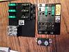
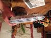
Step Eight Pictures Continued:

Step Nine
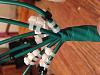
At this point your project is essentially complete, you can continue on to seal, paint, make your own modifications, or go ahead and install your DIY Fuse/Relay Box in your vehicle. Myself being particular about certain things, I wrapped the wires in matching electrical tape to keep things neat, then once installed you can use the electrical conduit to hide wires but keep them accessible. The result will look like it was professionally installed.
Notes:
This is actually my second design, and they both have worked flawlessly to my desires. My first was a working prototype, but the container had different dimensions making it take up a lot more space, used much more wire, and did not accomplish anything more than this second design. The idea is the same behind both, to save money and be closer to my jeep by creating something myself to match my needs. You can do this yourself, and alter the product however you want to match your needs. If you have any questions, comments, or improvements I would love to hear from you. I can be contacted by the username Zimmanski on either JK Forum | or www.w*******f****.com.
Step Nine
At this point your project is essentially complete, you can continue on to seal, paint, make your own modifications, or go ahead and install your DIY Fuse/Relay Box in your vehicle. Myself being particular about certain things, I wrapped the wires in matching electrical tape to keep things neat, then once installed you can use the electrical conduit to hide wires but keep them accessible. The result will look like it was professionally installed.
Notes:
This is actually my second design, and they both have worked flawlessly to my desires. My first was a working prototype, but the container had different dimensions making it take up a lot more space, used much more wire, and did not accomplish anything more than this second design. The idea is the same behind both, to save money and be closer to my jeep by creating something myself to match my needs. You can do this yourself, and alter the product however you want to match your needs. If you have any questions, comments, or improvements I would love to hear from you. I can be contacted by the username Zimmanski on either JK Forum | or www.w*******f****.com.
03-23-2014, 03:48 PM
#4
JK Newbie
Thread Starter
Also, I have a pages document and a word document of this write up that looks better and has a few more pictures, PM me if you would like me to email you either of them. Thanks for reading guys and let me know what you think!
03-29-2014, 04:03 PM
#7
JK Newbie
Thread Starter
Thanks guys, I really can't even describe how completely satisfied I am with this one haha, wasn't sure about it when I started but it is perfect.... And CHEAP!
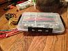
Before

Afters


Before
Afters
Trending Topics
04-07-2014, 07:18 PM
#9
JK Newbie
Thread Starter
Looks amazing! Really like your switches too, I have had a plan to use them for a while but no use yet haha. Bet you saved a ton of money with your DIY box. Do you know your total cost?
04-07-2014, 07:33 PM
#10
JK Enthusiast
$6- assorted grommets
$15- relays
$20- wire
$15- fuse block and circuit breaker
$20- fuses and connectors
So about $85. Very pleased and your write up made it super easy.