DIY Spod- Waytekwire
 07-28-2015, 10:33 AM
#1
JK Enthusiast
Thread Starter
Join Date: Jan 2015
Location: Des Moines
Posts: 111
Likes: 0
Received 0 Likes
on
0 Posts
I started a thread on this a year and a half ago on a different forum, but figured i would share it here, for anyone interested in building one.
Big thanks to White Dynamite for giving me the idea to use the Cooper Bussman relay/fuse panel.
The proper way of hooking up electrical accessories simply involves a switch, relay, fuse and wiring. That's all there is to it. This writeup will show you an easy way to wire up 5 circuits and avoid a lot of unnecessary wiring by using the Cooper Bussman relay/ fuse panel. Instead of wiring up 5 relays individually- you only need to supply the hot lead from the fuse to the relay, and the input/output wires to each relay.
This writeup utilizes 30 Amp relays- which is enough to run a 50" LED light bar, or most electric air compressors.
You should verify before hand, what circuits you already have and how many amps they will require- For LED lights- Add up total wattage of each light- (Total Watts/12volts=Amps Required)- Example- 100 watts/12= 8.33 Amps
This write up is for a simple 5 switched accessory circuit. If you need more than 5 accessories, you will need an additional relay/fuse panel and additional relays- or will up individual relays as needed. Cooper Bussman makes a 10 relay panel with 20 fuses. http://www.waytekwire.com/item/46354...-2-88-MM-DUAL/
Please read through the whole writeup twice before ordering anything….
This circuit passes 12 volts through the switch to the relay and then provides 12 volts out to the positive on the accessory. The accessory is then grounded to complete the circuit.
This circuit is Live all the time, regardless of ignition switch. You can install a “kill” switch on the power wire supplying 12 volts to the switches or run that wire off a 12 volt switched power wire. You can run a tap to the factory fuse panel for a switched source.
A Single Pole Single Throw switch of almost any type can be used. I chose Carling Rocker switches for this writeup.
You are free to decide where you want your switches, and where you want to mount the relay panel. It can be mounted under the hood, and has a waterproof cover included. You would want to plug any unused holes in the bottom of the panel. They sell plugs for the unused spots in the relay panel, i used extra seals and some silicone to waterproof mine.
if you want to mount it under the hood, there are brackets available- B028-7012-0-J $4.35 from waytekwire
A perfect switch mount for those with an automatic is Daystar’s KJ71034bk ($20) as it has 5 switch locations. The Daystar switch mount could be easily modified to mount to the upper windshield or anywhere.
Tools Required- wire cutters, wire strippers, wire crimpers, soldering gun, dremel or cutting tool (depending on where you mount your switches)
All parts listed are from waytekwire.com (unless otherwise noted)- there is a minimum order quantity on the smaller items.
Here's the parts for the relay panel
and here are the switches
The required components are:
46343 Relay/Fuse Panel $28.48
75730 Relays $14.55- Qty 5
31068 280 series Terminals (14-16ga) $5.84- Qty 50
39001 Terminal Seals $6.34- Qty 100
31713 Blue Female Quick Disconnect terminals $8.49- qty 50
46923 80 Amp Circuit Breaker $24.71
$88.41 + fuses, switches and wiring.
Depending on what you are hooking up, will determine what size fuses you use. You can go to any auto parts store to get the fuses as well in smaller quantites.
Most electric compressors will be 20-30 Amps, some higher. These relays are only rated at 30 Amp, and the mini style fuses only go to 30 Amp.
A few examples-
A 50" LED lightbar (288 watt) will draw 24 Amps.
Two windshield mount LED spotlights- 30 watts each = 5 amps total.
12 – 10 watt led rock lights = 10 Amps total.
You can fuse slightly higher than your expected total load per channel.
Mini Fuses or Circuit Breakers-
From waytekwire, fuses are:
46257 20A Fuses $5.60- Qty 50
46255 10A Fuses $5.60- Qty 50
Waytek has mini circuit breakers you can get instead of fuses.
46864- 25A Mini Circuit Breaker $6.84 (qty 3)
46862- 15A Mini Circuit Breaker $6.84 (qty 3)
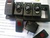
Switch examples-
Typical Carling Rocker Switches from waytekwire- light turns on only when switch is on.
44305 SPST Rocker Body Lighted $4.24ea- qty 5- $21.20
44352 Rocker Cover Red Lense $1.38ea- qty 5- $6.90- don't order these if you will get otrattw covers
Otrattw has dual lit led switch bodys ($10 each) and even have some with two different colored led’s. So one led can turn on when you turn the headlights on (illumination) and one led will turn on when the switch is activated.
OTRATTW :: Switch Body :: SPST ON/OFF :: Upper Independent Light
Wiring- Go to a local Car Audio Shop. You will need some 8 gauge wire for positive and ground, and then install the 80 Amp circuit breaker less than 12" from the battery positive post.
You will also need some 16 gauge wire to run from the relay panel to the switches- 7 conductors (1 for each switch, and one for 12volt feed from fuse 6, and 1 to bring the ground from the switches back to the ground terminal on the relay panel) Use automotive primary wire. Do not use speaker wire under the hood as the temperature rating on the wire is not high enough.
You will also want 16 gauge wire to run from the outputs of the relay panel to your accessories.
Misc- (4) 8ga ring terminals, (1) Blue (16ga) ring terminal, (5) Blue Male Fully Insulated .250 Quick Disconnects- Car audio store
About $35 for wiring, terminals
You can get the Covers in a lot of different colors and lense colors from waytekwire or you can get the printed specific covers from otrattw.com for $5 each, ie “Rock Lights, Beer, etc”
Before you begin, please note, once you insert the terminal into the back of the relay panel, it is pretty much permanent, so make sure your crimp on the terminal is good, solder it if you can.
** Test each crimp job by holding the terminal and pulling on the wire to see if it comes loose from the terminal.
Waytek has a terminal removal tool- if you need it. $9.46
Delphi 12094429 Metri-Pack Terminal Removal Tool for 150, 280, GT150, GT250 Series
Waytek also has a crimp tool for the terminals- I just used pliers to bend over the tabs and soldered it, but you could buy the crimp tool and get by without soldering. (at the time I did this writeup, I only knew of one crimper that was $84, but now there is one that is $23.28)
CrimpTool for 22-14 GA Delphi Metri-Pack 150, 280 & Weather-Pack Terminals
You will want to make all the connections to the back of the relay panel before installing the fuses or relays. If you will not be adding an accessory yet for all of the channels, don’t install the relay or fuse for the unused channel.
I ran a short pigtail with quick disconnects as my main output from the relay panel. This way, for every accessory I hooked up, I could ground the accessory close to the accessory, only run a positive wire from the accessory to the relay panel. That way the accessories can be disconnected or connected easily.
typical wire crimped (I did not have the actual crimp tool) to terminal (slide seal on before crimping) and solder the crimp.
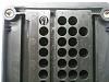
The back of the relay panel, terminal posts on the bottom- The left post on the back goes directly to the positive on the battery with a fuse holder – 8 gauge wire. This post and connection will need to be taped up completely so it does not get grounded out.
The right side post on the back goes to ground.
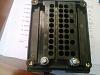
How the terminals go into the relay panel (note orientation of terminal in the hole)
Big thanks to White Dynamite for giving me the idea to use the Cooper Bussman relay/fuse panel.
The proper way of hooking up electrical accessories simply involves a switch, relay, fuse and wiring. That's all there is to it. This writeup will show you an easy way to wire up 5 circuits and avoid a lot of unnecessary wiring by using the Cooper Bussman relay/ fuse panel. Instead of wiring up 5 relays individually- you only need to supply the hot lead from the fuse to the relay, and the input/output wires to each relay.
This writeup utilizes 30 Amp relays- which is enough to run a 50" LED light bar, or most electric air compressors.
You should verify before hand, what circuits you already have and how many amps they will require- For LED lights- Add up total wattage of each light- (Total Watts/12volts=Amps Required)- Example- 100 watts/12= 8.33 Amps
This write up is for a simple 5 switched accessory circuit. If you need more than 5 accessories, you will need an additional relay/fuse panel and additional relays- or will up individual relays as needed. Cooper Bussman makes a 10 relay panel with 20 fuses. http://www.waytekwire.com/item/46354...-2-88-MM-DUAL/
Please read through the whole writeup twice before ordering anything….
This circuit passes 12 volts through the switch to the relay and then provides 12 volts out to the positive on the accessory. The accessory is then grounded to complete the circuit.
This circuit is Live all the time, regardless of ignition switch. You can install a “kill” switch on the power wire supplying 12 volts to the switches or run that wire off a 12 volt switched power wire. You can run a tap to the factory fuse panel for a switched source.
A Single Pole Single Throw switch of almost any type can be used. I chose Carling Rocker switches for this writeup.
You are free to decide where you want your switches, and where you want to mount the relay panel. It can be mounted under the hood, and has a waterproof cover included. You would want to plug any unused holes in the bottom of the panel. They sell plugs for the unused spots in the relay panel, i used extra seals and some silicone to waterproof mine.
if you want to mount it under the hood, there are brackets available- B028-7012-0-J $4.35 from waytekwire
A perfect switch mount for those with an automatic is Daystar’s KJ71034bk ($20) as it has 5 switch locations. The Daystar switch mount could be easily modified to mount to the upper windshield or anywhere.
Tools Required- wire cutters, wire strippers, wire crimpers, soldering gun, dremel or cutting tool (depending on where you mount your switches)
All parts listed are from waytekwire.com (unless otherwise noted)- there is a minimum order quantity on the smaller items.
Here's the parts for the relay panel
and here are the switches
The required components are:
46343 Relay/Fuse Panel $28.48
75730 Relays $14.55- Qty 5
31068 280 series Terminals (14-16ga) $5.84- Qty 50
39001 Terminal Seals $6.34- Qty 100
31713 Blue Female Quick Disconnect terminals $8.49- qty 50
46923 80 Amp Circuit Breaker $24.71
$88.41 + fuses, switches and wiring.
Depending on what you are hooking up, will determine what size fuses you use. You can go to any auto parts store to get the fuses as well in smaller quantites.
Most electric compressors will be 20-30 Amps, some higher. These relays are only rated at 30 Amp, and the mini style fuses only go to 30 Amp.
A few examples-
A 50" LED lightbar (288 watt) will draw 24 Amps.
Two windshield mount LED spotlights- 30 watts each = 5 amps total.
12 – 10 watt led rock lights = 10 Amps total.
You can fuse slightly higher than your expected total load per channel.
Mini Fuses or Circuit Breakers-
From waytekwire, fuses are:
46257 20A Fuses $5.60- Qty 50
46255 10A Fuses $5.60- Qty 50
Waytek has mini circuit breakers you can get instead of fuses.
46864- 25A Mini Circuit Breaker $6.84 (qty 3)
46862- 15A Mini Circuit Breaker $6.84 (qty 3)
Switch examples-
Typical Carling Rocker Switches from waytekwire- light turns on only when switch is on.
44305 SPST Rocker Body Lighted $4.24ea- qty 5- $21.20
44352 Rocker Cover Red Lense $1.38ea- qty 5- $6.90- don't order these if you will get otrattw covers
Otrattw has dual lit led switch bodys ($10 each) and even have some with two different colored led’s. So one led can turn on when you turn the headlights on (illumination) and one led will turn on when the switch is activated.
OTRATTW :: Switch Body :: SPST ON/OFF :: Upper Independent Light
Wiring- Go to a local Car Audio Shop. You will need some 8 gauge wire for positive and ground, and then install the 80 Amp circuit breaker less than 12" from the battery positive post.
You will also need some 16 gauge wire to run from the relay panel to the switches- 7 conductors (1 for each switch, and one for 12volt feed from fuse 6, and 1 to bring the ground from the switches back to the ground terminal on the relay panel) Use automotive primary wire. Do not use speaker wire under the hood as the temperature rating on the wire is not high enough.
You will also want 16 gauge wire to run from the outputs of the relay panel to your accessories.
Misc- (4) 8ga ring terminals, (1) Blue (16ga) ring terminal, (5) Blue Male Fully Insulated .250 Quick Disconnects- Car audio store
About $35 for wiring, terminals
You can get the Covers in a lot of different colors and lense colors from waytekwire or you can get the printed specific covers from otrattw.com for $5 each, ie “Rock Lights, Beer, etc”
Before you begin, please note, once you insert the terminal into the back of the relay panel, it is pretty much permanent, so make sure your crimp on the terminal is good, solder it if you can.
** Test each crimp job by holding the terminal and pulling on the wire to see if it comes loose from the terminal.
Waytek has a terminal removal tool- if you need it. $9.46
Delphi 12094429 Metri-Pack Terminal Removal Tool for 150, 280, GT150, GT250 Series
Waytek also has a crimp tool for the terminals- I just used pliers to bend over the tabs and soldered it, but you could buy the crimp tool and get by without soldering. (at the time I did this writeup, I only knew of one crimper that was $84, but now there is one that is $23.28)
CrimpTool for 22-14 GA Delphi Metri-Pack 150, 280 & Weather-Pack Terminals
You will want to make all the connections to the back of the relay panel before installing the fuses or relays. If you will not be adding an accessory yet for all of the channels, don’t install the relay or fuse for the unused channel.
I ran a short pigtail with quick disconnects as my main output from the relay panel. This way, for every accessory I hooked up, I could ground the accessory close to the accessory, only run a positive wire from the accessory to the relay panel. That way the accessories can be disconnected or connected easily.
typical wire crimped (I did not have the actual crimp tool) to terminal (slide seal on before crimping) and solder the crimp.
The back of the relay panel, terminal posts on the bottom- The left post on the back goes directly to the positive on the battery with a fuse holder – 8 gauge wire. This post and connection will need to be taped up completely so it does not get grounded out.
The right side post on the back goes to ground.
How the terminals go into the relay panel (note orientation of terminal in the hole)
Last edited by pvanweelden; 07-28-2015 at 11:25 AM.
 07-28-2015, 10:33 AM
#2
JK Enthusiast
Thread Starter
Join Date: Jan 2015
Location: Des Moines
Posts: 111
Likes: 0
Received 0 Likes
on
0 Posts
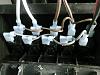
start with some 16 ga wire, and make some runs that will feed power from each fuse to each relay. Push the terminals in tight to the relay panel.
Fuse 1 will be for Relay 1, up to Fuse 5 for Relay 5.
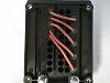
Fuse 6 - Green wire= 12 volts going to the switches. This is what makes the switches Live all the time, if you want switched, then run this to a switched source instead of from fuse 6.
Brown wire is the output from the relay going to the positive on your accessory.
White wire goes to the switch, and is the trigger for the relay (input)
plug center unused holes on each relay with the seals
Relay note- the red wires supply 12 volt constant fused to pin 30, pin 85 is grounded through relay panel, pin 86 is the white wire (relay input), and pin 87 is the brown wire (relay output)
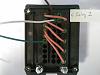
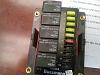
wire the rest of the relays up like relay 1. then flip it over and put relays and fuses in. NOTE- Relays are supposed to mount with lettering upside down as shown. Pin 85 has to go into upper left hand corner slot on relay panel.
switches- pin 3 -white wire going to relay input on switch one, different wire from switch 2 to relay 2, switch 3 to relay 3, etc
pin 2- green wire coming from fuse 6, you can daisy link this wire to feed all 5 switches.
pin 7 (these are the illuminated when on switches shown) this pin goes to ground, and you can connect all pin 7's together and take to ground (run 1 conductor back to relay panel to the ground post).
(i had some side crimp quick disconnects, i don't recommend those, straight quick disconnects are in the parts list)
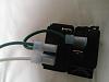
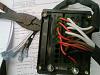
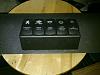
heres a relay panel all wired up
Fuse 1 will be for Relay 1, up to Fuse 5 for Relay 5.
Fuse 6 - Green wire= 12 volts going to the switches. This is what makes the switches Live all the time, if you want switched, then run this to a switched source instead of from fuse 6.
Brown wire is the output from the relay going to the positive on your accessory.
White wire goes to the switch, and is the trigger for the relay (input)
plug center unused holes on each relay with the seals
Relay note- the red wires supply 12 volt constant fused to pin 30, pin 85 is grounded through relay panel, pin 86 is the white wire (relay input), and pin 87 is the brown wire (relay output)
wire the rest of the relays up like relay 1. then flip it over and put relays and fuses in. NOTE- Relays are supposed to mount with lettering upside down as shown. Pin 85 has to go into upper left hand corner slot on relay panel.
switches- pin 3 -white wire going to relay input on switch one, different wire from switch 2 to relay 2, switch 3 to relay 3, etc
pin 2- green wire coming from fuse 6, you can daisy link this wire to feed all 5 switches.
pin 7 (these are the illuminated when on switches shown) this pin goes to ground, and you can connect all pin 7's together and take to ground (run 1 conductor back to relay panel to the ground post).
(i had some side crimp quick disconnects, i don't recommend those, straight quick disconnects are in the parts list)
heres a relay panel all wired up
Last edited by pvanweelden; 07-28-2015 at 10:51 AM.
07-28-2015, 10:34 AM
#3
JK Enthusiast
Thread Starter
Join Date: Jan 2015
Location: Des Moines
Posts: 111
Likes: 0
Received 0 Likes
on
0 Posts
Room for future accessories- put a fuse in fuse 7,8,9,or 10 and run it to an accessory that doesn't need a relay, like a cb radio.
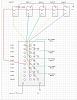
Here's a wiring schematic for the relay panel and switches- note this is the back of the panel and the back of the switches. Line colors on layout do not match wire colors i used in pictures. From top of switch down is Pin 7, Pin 2, Pin 3. Pin 7 is ground, Pin 2 is power in, Pin 3 is power out
and if you know up front you will want more than 5 relays/circuits- Cooper Bussman has a 10 relay/40 fuse panel from waytekwire.
Installation procedure would be similar to shown here, but I don't have one to confirm 100%.
http://www.waytekwire.com/item/46354...-2-88-MM-DUAL/
If you decide to use the dual lit led switch bodies from otrattw, you need to run one more wire from the switches to an illumination source wire (20 gauge orange wire with gray stripe at power window controls- Jeep JK)
Here is how you would wire up the double lit led switches-
Here's a Daystar pic of the 5 switch panel for automatics-
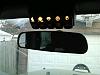
i took the Daystar and cut it-
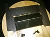
then cut a hole in the upper windshield trim-
Here's a wiring schematic for the relay panel and switches- note this is the back of the panel and the back of the switches. Line colors on layout do not match wire colors i used in pictures. From top of switch down is Pin 7, Pin 2, Pin 3. Pin 7 is ground, Pin 2 is power in, Pin 3 is power out
and if you know up front you will want more than 5 relays/circuits- Cooper Bussman has a 10 relay/40 fuse panel from waytekwire.
Installation procedure would be similar to shown here, but I don't have one to confirm 100%.
http://www.waytekwire.com/item/46354...-2-88-MM-DUAL/
If you decide to use the dual lit led switch bodies from otrattw, you need to run one more wire from the switches to an illumination source wire (20 gauge orange wire with gray stripe at power window controls- Jeep JK)
Here is how you would wire up the double lit led switches-
Here's a Daystar pic of the 5 switch panel for automatics-
i took the Daystar and cut it-
then cut a hole in the upper windshield trim-
Last edited by pvanweelden; 07-28-2015 at 10:55 AM.
07-28-2015, 10:35 AM
#4
JK Enthusiast
Thread Starter
Join Date: Jan 2015
Location: Des Moines
Posts: 111
Likes: 0
Received 0 Likes
on
0 Posts
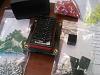
switches all wired up (not the same colored wires as above) (again, don't use the pigtail connectors)
Switches-
Relay panel behind glove box- Cover positive post with tape to keep from shorting out
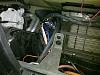
When you run any wiring under the hood, use wireloom. there's a hole behind the battery on the firewall perfect for running wires.
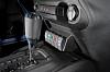
a alternative spot for switches (courtesy of noroad)
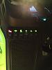
Switches-
Relay panel behind glove box- Cover positive post with tape to keep from shorting out
When you run any wiring under the hood, use wireloom. there's a hole behind the battery on the firewall perfect for running wires.
a alternative spot for switches (courtesy of noroad)
Last edited by pvanweelden; 07-28-2015 at 11:29 AM.
07-28-2015, 10:35 AM
#5
JK Enthusiast
Thread Starter
Join Date: Jan 2015
Location: Des Moines
Posts: 111
Likes: 0
Received 0 Likes
on
0 Posts
and last week, a user made a series of videos from my original writeup- Sunny501
Introduction of DIY sPOD
https://youtu.be/zWoYn4csc3o
Part 1 Relay Panel
https://youtu.be/gylXb1XwGZM
Part 2 Switch Panel
https://youtu.be/i54sHJJZgRY
Part 3 Installation
https://youtu.be/ZSvaVNWmin0
Dash Panels Removal
https://youtu.be/HTz1U6CiPlE
Introduction of DIY sPOD
https://youtu.be/zWoYn4csc3o
Part 1 Relay Panel
https://youtu.be/gylXb1XwGZM
Part 2 Switch Panel
https://youtu.be/i54sHJJZgRY
Part 3 Installation
https://youtu.be/ZSvaVNWmin0
Dash Panels Removal
https://youtu.be/HTz1U6CiPlE
Last edited by pvanweelden; 07-28-2015 at 11:10 AM.
07-28-2015, 10:36 AM
#6
JK Enthusiast
Thread Starter
Join Date: Jan 2015
Location: Des Moines
Posts: 111
Likes: 0
Received 0 Likes
on
0 Posts
If you want to get creative- https://www.jk-forum.com/forums/jk-w...m-spod-307789/
i recently purchased the crimper http://www.waytekwire.com/item/533/C...ED-METRI-PACK/
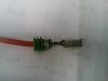
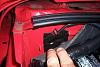
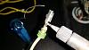
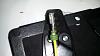
so here's a few pics on how to use it. First strip the insulation, twist strands of wire together with your fingers, solder the wires, SLIDE SEAL on the wire before crimping.
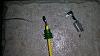
place the terminal end on the wire, and place in the crimp tool. carefully line up and squeeze tool handles together.
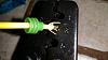
Slide seal tight towards the crimp, place in crimp tool, squeeze handles together
Then solder the wire to the terminal end. heat up terminal with soldering iron, apply solder to top.
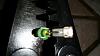
Should look like this when done.
i recently purchased the crimper http://www.waytekwire.com/item/533/C...ED-METRI-PACK/
so here's a few pics on how to use it. First strip the insulation, twist strands of wire together with your fingers, solder the wires, SLIDE SEAL on the wire before crimping.
place the terminal end on the wire, and place in the crimp tool. carefully line up and squeeze tool handles together.
Slide seal tight towards the crimp, place in crimp tool, squeeze handles together
Then solder the wire to the terminal end. heat up terminal with soldering iron, apply solder to top.
Should look like this when done.
Last edited by pvanweelden; 08-04-2015 at 08:16 AM.
Trending Topics
 08-14-2015, 09:30 PM
#10
JK Enthusiast
Thread Starter
Join Date: Jan 2015
Location: Des Moines
Posts: 111
Likes: 0
Received 0 Likes
on
0 Posts
Been working with Erich Wollner on a few ideas for adding a bluetooth controller for relays, and been making some good progress on it. Programming the controller
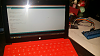
And an example of what my phone app (or tablet or android head unit app) would look like (the pictures can be user selected)
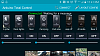
And an example of what my phone app (or tablet or android head unit app) would look like (the pictures can be user selected)