
Hard wired winch control

Thread Starter
JK Enthusiast
Joined: Nov 2010
Posts: 274
Likes: 0
From: Sacramento, Ca
I wanted to hard wire the controls for my winch into the cab of the jeep. So after reading a few other write ups and posts I figured I would give it a try. I wanted the winch only useable from the cab with the ignition on, and be able to lock out the control switches so they couldn�t be accidentally operated. So here is what I did. Sorry about the crappy photos
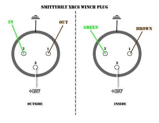
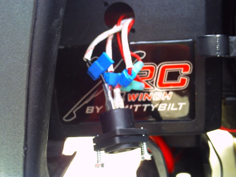
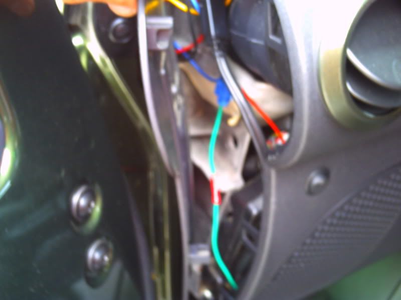
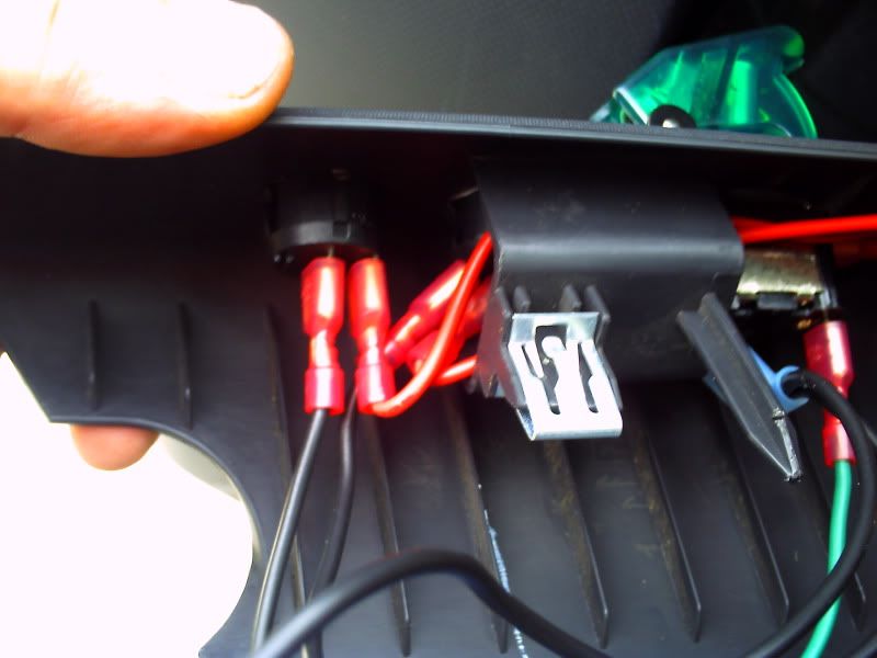
First disconnect the battery. Then remove the remote control socket or open solenoid housing. I unbolted the remote control socket and pulled it out (a lot easier for me because where I have it located). On the SmittyBilt 8000 XRC there are 3 wires leading from the remote control socket. One black wire (12V) and two red wires which control the solenoid. The black (12V) powers the remote so you don�t need it. Tap into the two red wires, run the wires you connect to them thru the engine bay, then thru the firewall to where ever the switches are going to be located. I ran mine to the A pillar.
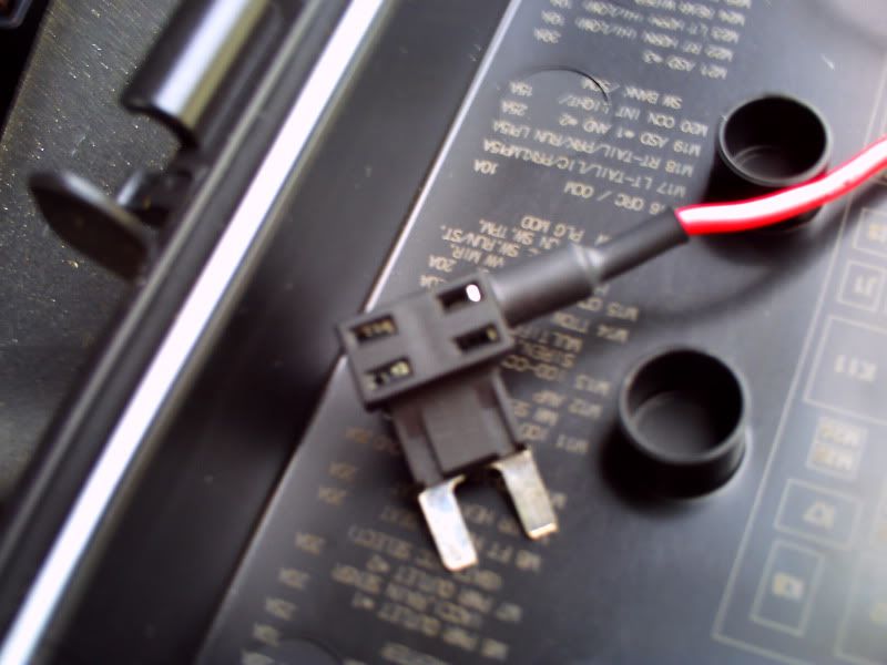
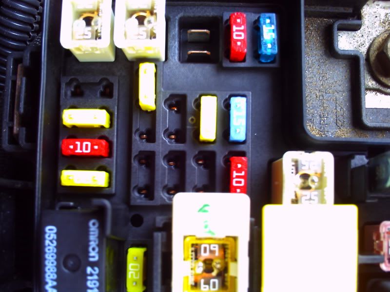
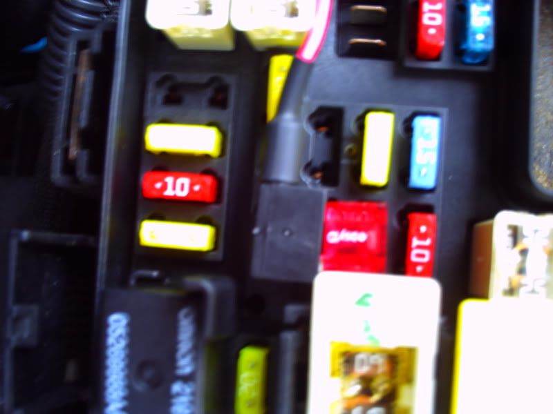
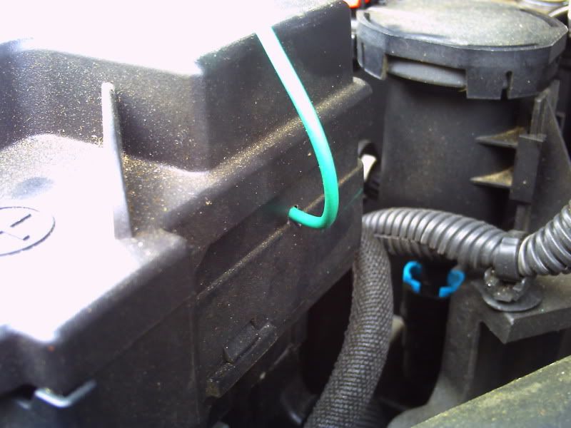
I wanted to make it so the winch could only be used with the ignition on. So I used one of the unused heated seat fuse openings (M8 or M9). Using an Ad-a-fuse or tap-a fuse, plug into one of the open fuse receptacles. I drilled a small hole and ran the wire out of the fuse box across the back of the engine bay and thru the firewall on the driver�s side.
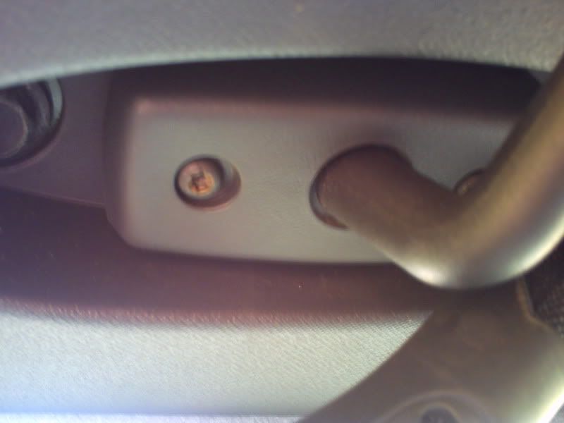
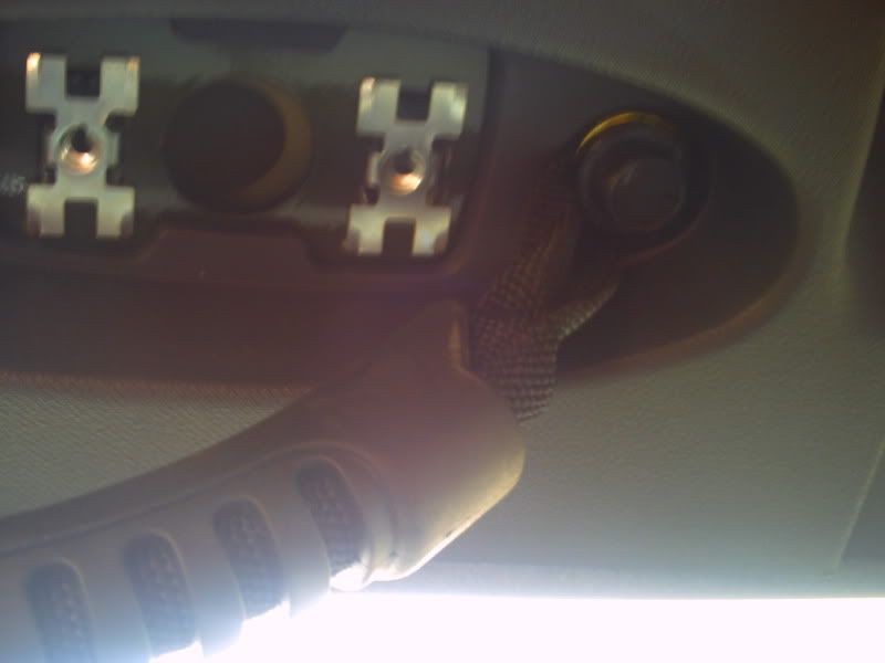
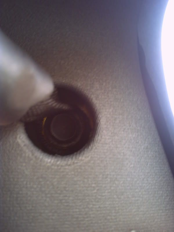
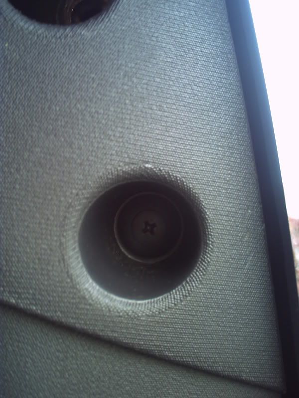
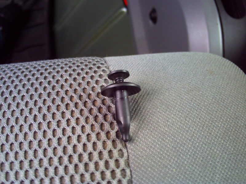
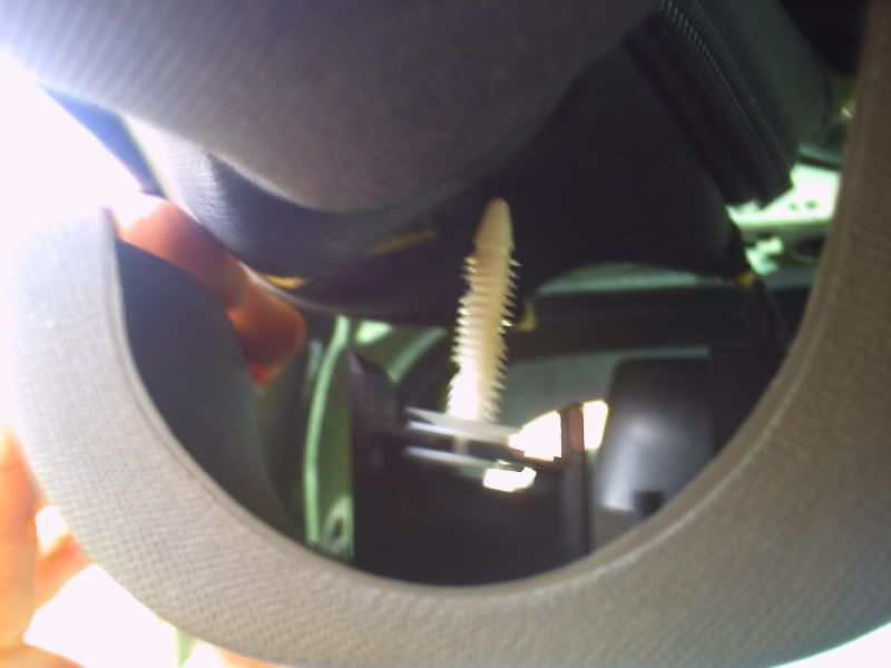
Pull away side trim piece. Unscrew the two T-20 visor screws, set visor aside. Unbolt the three 13 mm bolts holding the top trim piece on. Unscrew and pull out the little plastic retainer in the second hole. Now pull down on the trim, it�s still being held on with a barbed plastic fastener. Then pull the A-pillar trim piece off, it�s held in with two metal clips.
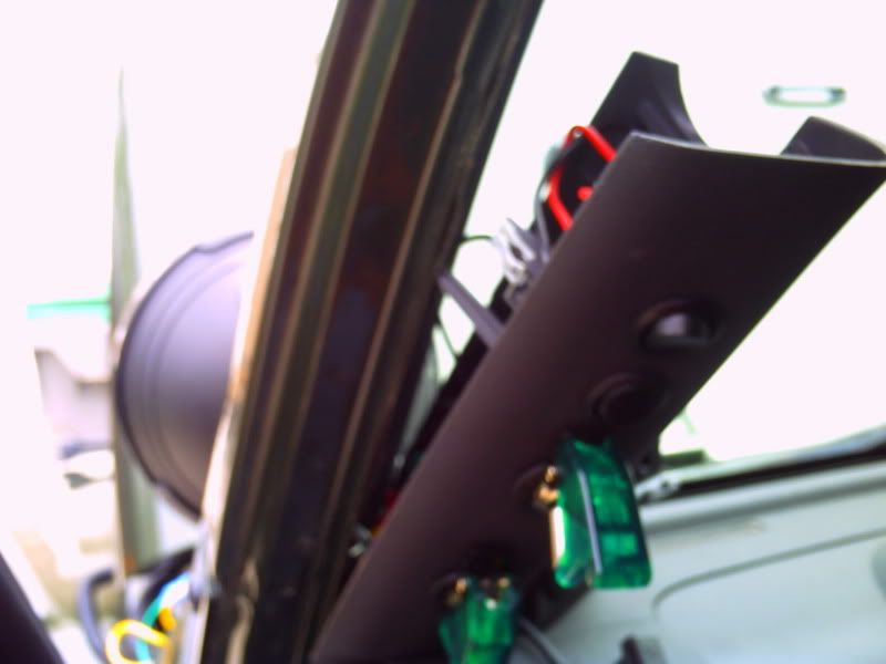
For my switches I used two momentary rockers to actuate the winch and a green hooded led toggle to power the rockers.
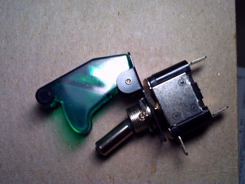
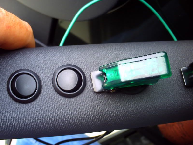
The rockers I used fit perfectly in a � inch hole. The toggle I think was 3/8th inch, I used a step bit but I�m pretty sure it was 3/8th. Figure out where you want them, and get to drilling. I eyeballed mine so they are a hair off each other, if it really starts to bother me I don�t think that trim piece is very expensive to replace.
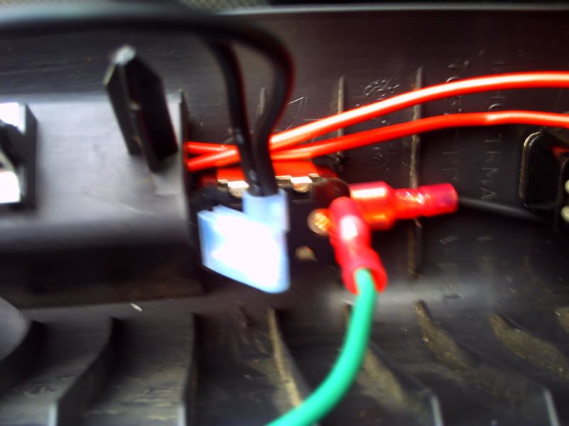
Attach toggle to trim piece. I used a couple neoprene washers on the front and back of the trim piece. Ground the switch to the frame, and then connect the wire that was run from the fuse box. Now pigtail two power leads off of the toggle, these will power the two rockers. It�s easier to wait till the end after everything is hooked before you push the rockers into the trim. So push the power leads thru the corresponding holes and connect to the rockers. Now take the two wires you ran earlier from the solenoid and connect to the respective switches. Connect battery, start engine, turn the toggle on and test the rockers for which direction they control and switch their position if necessary. Turn off toggle, push rockers into position on trim piece and tidy up the wires.
Now just replace everything in reverse. Also it�s a good idea to use wire looms to protect all the wiring that�s passing thru the engine bay.
Disclaimer: This is not professional advice; follow at your own risk.
First disconnect the battery. Then remove the remote control socket or open solenoid housing. I unbolted the remote control socket and pulled it out (a lot easier for me because where I have it located). On the SmittyBilt 8000 XRC there are 3 wires leading from the remote control socket. One black wire (12V) and two red wires which control the solenoid. The black (12V) powers the remote so you don�t need it. Tap into the two red wires, run the wires you connect to them thru the engine bay, then thru the firewall to where ever the switches are going to be located. I ran mine to the A pillar.
I wanted to make it so the winch could only be used with the ignition on. So I used one of the unused heated seat fuse openings (M8 or M9). Using an Ad-a-fuse or tap-a fuse, plug into one of the open fuse receptacles. I drilled a small hole and ran the wire out of the fuse box across the back of the engine bay and thru the firewall on the driver�s side.
Pull away side trim piece. Unscrew the two T-20 visor screws, set visor aside. Unbolt the three 13 mm bolts holding the top trim piece on. Unscrew and pull out the little plastic retainer in the second hole. Now pull down on the trim, it�s still being held on with a barbed plastic fastener. Then pull the A-pillar trim piece off, it�s held in with two metal clips.
For my switches I used two momentary rockers to actuate the winch and a green hooded led toggle to power the rockers.
The rockers I used fit perfectly in a � inch hole. The toggle I think was 3/8th inch, I used a step bit but I�m pretty sure it was 3/8th. Figure out where you want them, and get to drilling. I eyeballed mine so they are a hair off each other, if it really starts to bother me I don�t think that trim piece is very expensive to replace.
Attach toggle to trim piece. I used a couple neoprene washers on the front and back of the trim piece. Ground the switch to the frame, and then connect the wire that was run from the fuse box. Now pigtail two power leads off of the toggle, these will power the two rockers. It�s easier to wait till the end after everything is hooked before you push the rockers into the trim. So push the power leads thru the corresponding holes and connect to the rockers. Now take the two wires you ran earlier from the solenoid and connect to the respective switches. Connect battery, start engine, turn the toggle on and test the rockers for which direction they control and switch their position if necessary. Turn off toggle, push rockers into position on trim piece and tidy up the wires.
Now just replace everything in reverse. Also it�s a good idea to use wire looms to protect all the wiring that�s passing thru the engine bay.
Disclaimer: This is not professional advice; follow at your own risk.
JK Enthusiast
Joined: Aug 2010
Posts: 268
Likes: 2
From: Tucson
Interesting write-up. Thanks for the information.
I'm assuming that you could still use the hand control if you needed to (as you appear to be paralleling the conductors.
Do you know what the current requirements are for the +12 source? I'm guessing it's fairly low, in that all your doing is pulling in a solenoid.
I'm assuming that you could still use the hand control if you needed to (as you appear to be paralleling the conductors.
Do you know what the current requirements are for the +12 source? I'm guessing it's fairly low, in that all your doing is pulling in a solenoid.
JK Junkie
Joined: Jan 2011
Posts: 3,449
Likes: 2
From: Newport news, va
Originally Posted by Jhen
I wanted to hard wire the controls for my winch into the cab of the jeep. So after reading a few other write ups and posts I figured I would give it a try. I wanted the winch only useable from the cab with the ignition on, and be able to lock out the control switches so they couldn�t be accidentally operated. So here is what I did. Sorry about the crappy photos
First disconnect the battery. Then remove the remote control socket or open solenoid housing. I unbolted the remote control socket and pulled it out (a lot easier for me because where I have it located). On the SmittyBilt 8000 XRC there are 3 wires leading from the remote control socket. One black wire (12V) and two red wires which control the solenoid. The black (12V) powers the remote so you don�t need it. Tap into the two red wires, run the wires you connect to them thru the engine bay, then thru the firewall to where ever the switches are going to be located. I ran mine to the A pillar.
I wanted to make it so the winch could only be used with the ignition on. So I used one of the unused heated seat fuse openings (M8 or M9). Using an Ad-a-fuse or tap-a fuse, plug into one of the open fuse receptacles. I drilled a small hole and ran the wire out of the fuse box across the back of the engine bay and thru the firewall on the driver�s side.
Pull away side trim piece. Unscrew the two T-20 visor screws, set visor aside. Unbolt the three 13 mm bolts holding the top trim piece on. Unscrew and pull out the little plastic retainer in the second hole. Now pull down on the trim, it�s still being held on with a barbed plastic fastener. Then pull the A-pillar trim piece off, it�s held in with two metal clips.
For my switches I used two momentary rockers to actuate the winch and a green hooded led toggle to power the rockers.
The rockers I used fit perfectly in a � inch hole. The toggle I think was 3/8th inch, I used a step bit but I�m pretty sure it was 3/8th. Figure out where you want them, and get to drilling. I eyeballed mine so they are a hair off each other, if it really starts to bother me I don�t think that trim piece is very expensive to replace.
Attach toggle to trim piece. I used a couple neoprene washers on the front and back of the trim piece. Ground the switch to the frame, and then connect the wire that was run from the fuse box. Now pigtail two power leads off of the toggle, these will power the two rockers. It�s easier to wait till the end after everything is hooked before you push the rockers into the trim. So push the power leads thru the corresponding holes and connect to the rockers. Now take the two wires you ran earlier from the solenoid and connect to the respective switches. Connect battery, start engine, turn the toggle on and test the rockers for which direction they control and switch their position if necessary. Turn off toggle, push rockers into position on trim piece and tidy up the wires.
Now just replace everything in reverse. Also it�s a good idea to use wire looms to protect all the wiring that�s passing thru the engine bay.
Disclaimer: This is not professional advice; follow at your own risk.
 ....
....
Thread Starter
JK Enthusiast
Joined: Nov 2010
Posts: 274
Likes: 0
From: Sacramento, Ca
Interesting write-up. Thanks for the information.
I'm assuming that you could still use the hand control if you needed to (as you appear to be paralleling the conductors.
Do you know what the current requirements are for the +12 source? I'm guessing it's fairly low, in that all your doing is pulling in a solenoid.
I'm assuming that you could still use the hand control if you needed to (as you appear to be paralleling the conductors.
Do you know what the current requirements are for the +12 source? I'm guessing it's fairly low, in that all your doing is pulling in a solenoid.
I dont know what the draw is, it cant be a whole lot. I'm using a 10 amp fuse and I'm sure I could get away with a 5.
 I cant see the 10,000 being any diffrent.
Thread Starter
JK Enthusiast
Joined: Nov 2010
Posts: 274
Likes: 0
From: Sacramento, Ca
Trending Topics
JK Enthusiast
Joined: Aug 2010
Posts: 162
Likes: 0
From: East Texas
Awesome! I've gotta do this! As soon as my bumper gets in. Sorry not really meaning to Jack the thread but I just purchased a 12,000 xrc. Do you think it will be the same? (Here's where the jacking comes in to play) How does the xrc hold up in being submerged in water/mudd? Is there away to "water proof" the control box?