
View Poll Results: Interested in new headlights
Yes


944
94.40%
No


56
5.60%
Voters: 1000. You may not vote on this poll
New JK Headlights


JK Enthusiast
Joined: Nov 2009
Posts: 162
Likes: 0
From: Redmond, WA
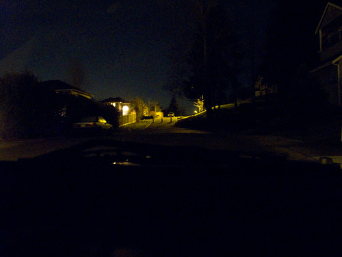
Alright, here are my attempts at taking pictures of the light. I used a Canon G11 set to automatic mode, no exposure compensation, flash off. The camera was set on top of the console above the radio, and the Jeep was parked on a slight hill aiming at another hill. After loading the pics on my computer I did not do any adjustments.
If you go to Flickr you can see the pics twice as large, plus the exif data in case you really want to think about how much light there is.
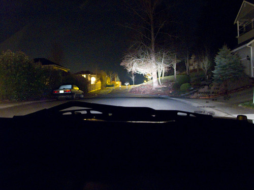
First our neighborhood with the Jeep lights off.
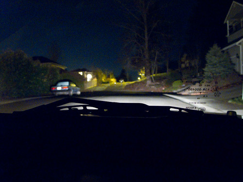
Next I turned the fog lights on.
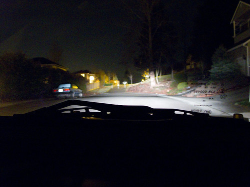
Then I turned the new IPFs on to 'normal'.
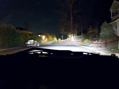
Then IPFss at 'normal' + fogs.
Then the IPFs on 'high'.
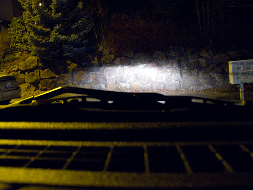
Then I moved the Jeep to be pointing at a rock wall across the street. I backed up until there was like 20 feet or so between the lights and the wall.
Shot the wall with 'normal'.
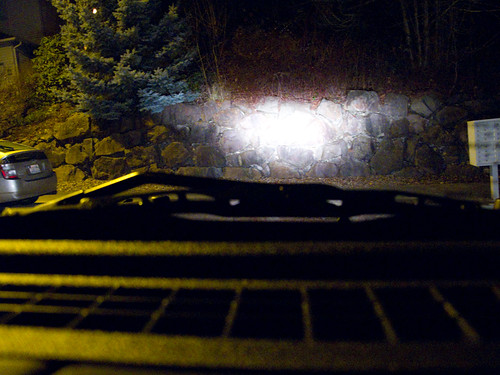
Shot of the wall with 'high'.
If you go to Flickr you can see the pics twice as large, plus the exif data in case you really want to think about how much light there is.
First our neighborhood with the Jeep lights off.
Next I turned the fog lights on.
Then I turned the new IPFs on to 'normal'.
Then IPFss at 'normal' + fogs.
Then the IPFs on 'high'.
Then I moved the Jeep to be pointing at a rock wall across the street. I backed up until there was like 20 feet or so between the lights and the wall.
Shot the wall with 'normal'.
Shot of the wall with 'high'.
JK Enthusiast
Joined: Dec 2006
Posts: 494
Likes: 0
From: Spokane WA
JK Enthusiast
Joined: Dec 2006
Posts: 494
Likes: 0
From: Spokane WA
[QUOTE=paulp575;1528502]Mine is a 2007 Rubicon with a build date of Feb 2007.
Original connector:
Replacement connector:
Notice the difference between the ridges on the left and right edges of the connector (these will be shortened) and the width of the center locking piece.
Modified replacement connector:
We had to shorten the ridges on the left and right sides of the connector and trim (by narrowing) the center piece of plastic that holds the two connector together.
Last edited by paulp575; Jan 24, 2010 at 03:22 PM. Reason: Pictures are now viewable here; no need for link to posted pictures!
 Thanks again to David for putting this kit together.
JK Enthusiast
Joined: Dec 2006
Posts: 494
Likes: 0
From: Spokane WA
That is exactly what we noticed at first - it would not go in all the way. I suspect that's why X-caiver used electrical tape to keep the connectors together.
We just cut out the "offending" ridges and narrowed the center piece and they clipped together like they were supposed to do!
I think over time the taped together connectors may come apart. Ever seen what an electrically-taped connection looks like years later? And we subject these connections to water and dirt!

