The Cobra POD - Auxiliary Electrical Control
 03-31-2011, 03:39 PM
#1
JK Enthusiast
Thread Starter
Join Date: Jul 2008
Location: Houston / Spring, TX
Posts: 285
Likes: 0
Received 0 Likes
on
0 Posts
So I finally had enough time to finish assembling my electrical switches and distribution and got them mounted in the jeep. This setup is based on my friend Rescue1's core connection strategy, i.e. Battery > 150 amp Fuse > 6 Outlet Fuse Block rated at 150 amp total > 6 relays connected to in-dash switches and the individual auxiliary items to be controlled.
I have seen various versions of electrical setups and locations posted in different write-up threads and I used ideas from each of those to come up with this solution. So a big thanks first to those other guys/gals that have taken the time to document what they did.
So, first things first. I had done a similar wiring setup with my friend on my previous 2 door jeep, but one thing that always bothered me was that the relays and fuse block were exposed to the engine bay environment. Not a major deal, but I wanted to box them up and protect them a little. The obvious location for the box, as several others have done, is to put it next to the battery by the existing fuse box, but my solenoid box for my winch was already occupying that area. So, I tested out some options for mounting on top of the fuse box but I found that there wasn't enough room there under the hood.
So I moved over to the driver's side of the bay and found a spot behind the windshield washer fluid reservoir. The only issue is the existing mass of electrical cabling along the lower part of that space. So a box placed there would have to float above the cabling and be supported.
Technical Requirements -
So this is what I came up with -
The Cobra POD
Parts List -
150 Amp Fuse and holder + plus 4 ga wire (package deal) - ebay ~$50
6 Scosche SPDT Relays - ebay ~$15
10 ga. wire, about half of a 20 ft spool, autozone - $19
16 ga wire, roughly 20 ft, autozone - ~$10
1 8-position power distribution / barrier strip, radioshack - ~$4 (Note you can use a 6 position they were just out of them that day)
Link: www.radioshack.com/product/index.jsp?productId=2103229
1 Jumper for above barrier strip, radioshack - ~$2 (this bridges the power from the heated seat fuse tap to all of the switches)
Link: www.radioshack.com/product/index.jsp?productId=2103227
2 L Brackets bent to shape, Home Depot ~$6
1 Add-a-fuse connection, Autozone - ~$3
Plus several quick connects and end terminations for all of the connections. ~$20
AllElectronics.com order -
10 LRS-30G (12V ROCKER SWITCH W/ GREEN LED - (LRS-30G)) $22.00 (I got a few extras as I have bad experience with the LEDs burning out)
10 SLT-34 (3/4" DIAMETER SPLIT-LOOM TUBING - (SLT-34)) $2.90
10 SLT-12 (1/2" DIA. SPLIT LOOM TUBING - (SLT-12)) $1.90
10 SLT-14 (1/4" SPLIT LOOM TUBING - (SLT-14)) $1.20
10 SLT-38 (3/8" DIA. SPLIT LOOM TUBING - (SLT-38)) $1.50
1 MBF-24 (PROJECT BOX W/ MOUNTING FLANGE, 7.31" X 3.75" X 2.08" - (MBF-24)) $5.45
1 MBF-22 (PROJECT BOX W/ MTNG FLANGE, 6.14" X 2.64" X 1.57" - (MBF-22)) $3.50
50 6225 (1/4" FULLY INSULATED FEMALE, BLUE - (6225)) $5.40
50 9108 (#8 SPADE TERMINAL, RED - (9108)) $3.00
Total = $172.85
Note: The above does include some extra stuff that I bought as I know I will have additional wiring projects. I estimate total cost spent on this project alone was about $150. Which is significantly cheaper than some of the other options I priced out.
And this is the end result -
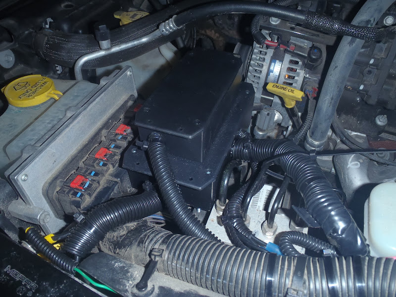
The support for the POD (drilling that second hole by hand was a PITA!!!)-

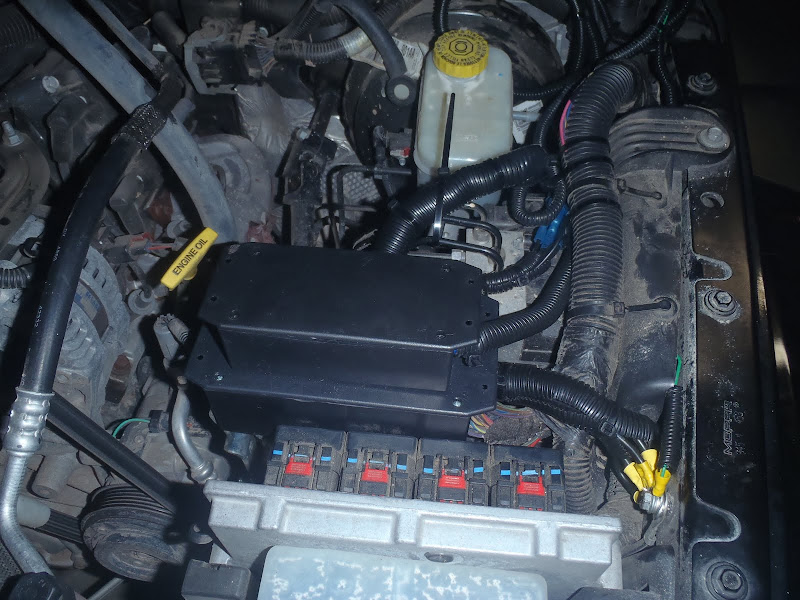
The guts: (6 position fuse block and relays, the connection wires with blue tape pass from the fuses in the top box through the holes in the "floor" and down into the lower box to power the relays. I tried to find a single project box to fit this space to contain all of the components but nothing fit just right) -

The 150 amp fuse (must be placed close to the battery to be effective, the second fuse holder is for my inverter to be installed after I order more 4 ga wire) -

The switches and the wiring in the cab / barrier strip w/ jumper (see above for updated link for these items) -

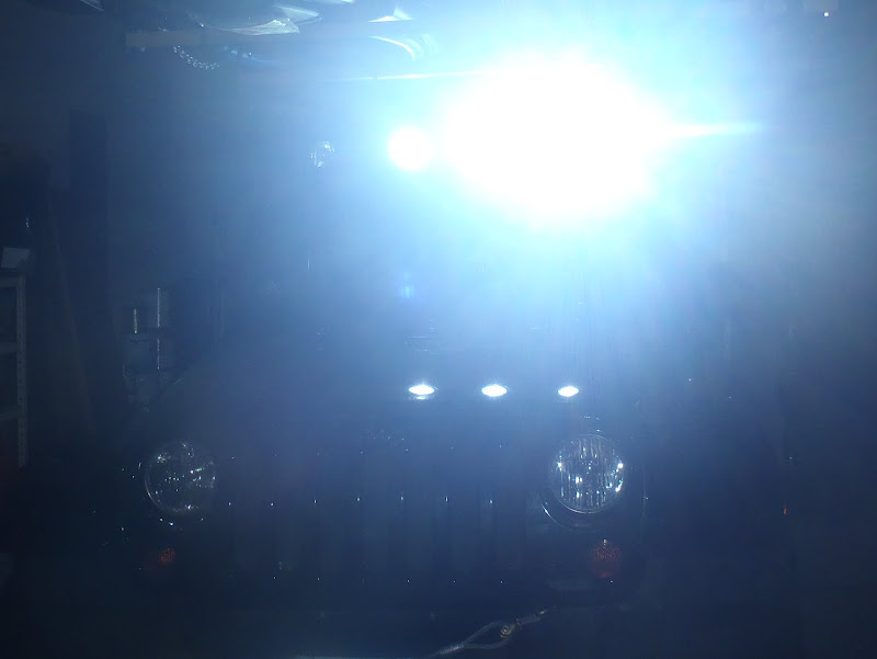
And finally, my HID lights connected (I need to replace one bulb) -
Edit: Added a pic of the add-a-fuse connection in the main fuse box. This is the power source for the distribution strip and switches. The add-a-fuse plugs into the empty heated seats fuse position, M8, with its on separate fuse. You should be able to find the M8 position by the fuse layout on the underside of your fuse box cover, or if you can't read yours just google jeep Jk fuse box layout. This slot is only powered when the key is turned to ignition so no chance of draining your battery when you don't have the key in.
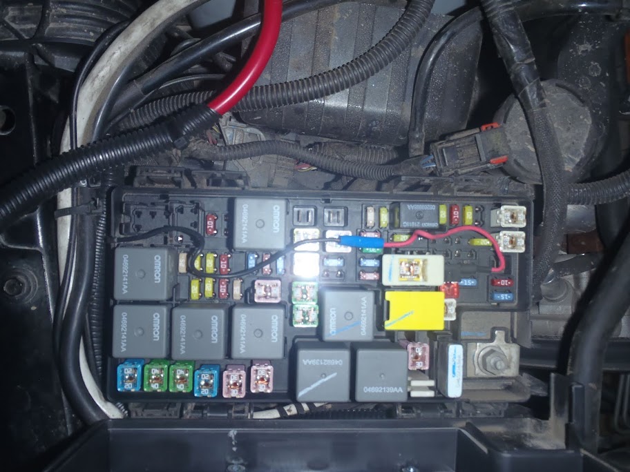
This is what the add-a-fuse looks like. Make sure you get the right size.

Let me know if you have any questions
I have seen various versions of electrical setups and locations posted in different write-up threads and I used ideas from each of those to come up with this solution. So a big thanks first to those other guys/gals that have taken the time to document what they did.
So, first things first. I had done a similar wiring setup with my friend on my previous 2 door jeep, but one thing that always bothered me was that the relays and fuse block were exposed to the engine bay environment. Not a major deal, but I wanted to box them up and protect them a little. The obvious location for the box, as several others have done, is to put it next to the battery by the existing fuse box, but my solenoid box for my winch was already occupying that area. So, I tested out some options for mounting on top of the fuse box but I found that there wasn't enough room there under the hood.
So I moved over to the driver's side of the bay and found a spot behind the windshield washer fluid reservoir. The only issue is the existing mass of electrical cabling along the lower part of that space. So a box placed there would have to float above the cabling and be supported.
Technical Requirements -
- Protected enclosure for sensitive components in engine bay
- Maximum of 6 connections for auxiliary electrical items (windshield lights, on-board air, rock lights, rear lights planned plus 2 spares)
- Ignition on power only, I don't want to run my battery down or have some idiot mess with the switches when my doors are off.
- Maximum 30 amp connection per item (my 800 watt inverter will not be connected through this).
So this is what I came up with -
The Cobra POD
Parts List -
150 Amp Fuse and holder + plus 4 ga wire (package deal) - ebay ~$50
6 Scosche SPDT Relays - ebay ~$15
10 ga. wire, about half of a 20 ft spool, autozone - $19
16 ga wire, roughly 20 ft, autozone - ~$10
1 8-position power distribution / barrier strip, radioshack - ~$4 (Note you can use a 6 position they were just out of them that day)
Link: www.radioshack.com/product/index.jsp?productId=2103229
1 Jumper for above barrier strip, radioshack - ~$2 (this bridges the power from the heated seat fuse tap to all of the switches)
Link: www.radioshack.com/product/index.jsp?productId=2103227
2 L Brackets bent to shape, Home Depot ~$6
1 Add-a-fuse connection, Autozone - ~$3
Plus several quick connects and end terminations for all of the connections. ~$20
AllElectronics.com order -
10 LRS-30G (12V ROCKER SWITCH W/ GREEN LED - (LRS-30G)) $22.00 (I got a few extras as I have bad experience with the LEDs burning out)
10 SLT-34 (3/4" DIAMETER SPLIT-LOOM TUBING - (SLT-34)) $2.90
10 SLT-12 (1/2" DIA. SPLIT LOOM TUBING - (SLT-12)) $1.90
10 SLT-14 (1/4" SPLIT LOOM TUBING - (SLT-14)) $1.20
10 SLT-38 (3/8" DIA. SPLIT LOOM TUBING - (SLT-38)) $1.50
1 MBF-24 (PROJECT BOX W/ MOUNTING FLANGE, 7.31" X 3.75" X 2.08" - (MBF-24)) $5.45
1 MBF-22 (PROJECT BOX W/ MTNG FLANGE, 6.14" X 2.64" X 1.57" - (MBF-22)) $3.50
50 6225 (1/4" FULLY INSULATED FEMALE, BLUE - (6225)) $5.40
50 9108 (#8 SPADE TERMINAL, RED - (9108)) $3.00
Total = $172.85
Note: The above does include some extra stuff that I bought as I know I will have additional wiring projects. I estimate total cost spent on this project alone was about $150. Which is significantly cheaper than some of the other options I priced out.
And this is the end result -
The support for the POD (drilling that second hole by hand was a PITA!!!)-
The guts: (6 position fuse block and relays, the connection wires with blue tape pass from the fuses in the top box through the holes in the "floor" and down into the lower box to power the relays. I tried to find a single project box to fit this space to contain all of the components but nothing fit just right) -
The 150 amp fuse (must be placed close to the battery to be effective, the second fuse holder is for my inverter to be installed after I order more 4 ga wire) -
The switches and the wiring in the cab / barrier strip w/ jumper (see above for updated link for these items) -
And finally, my HID lights connected
(I need to replace one bulb) -Edit: Added a pic of the add-a-fuse connection in the main fuse box. This is the power source for the distribution strip and switches. The add-a-fuse plugs into the empty heated seats fuse position, M8, with its on separate fuse. You should be able to find the M8 position by the fuse layout on the underside of your fuse box cover, or if you can't read yours just google jeep Jk fuse box layout. This slot is only powered when the key is turned to ignition so no chance of draining your battery when you don't have the key in.
This is what the add-a-fuse looks like. Make sure you get the right size.
Let me know if you have any questions
Last edited by JKCobra; 04-24-2011 at 09:07 AM. Reason: Updated to answer a few questions
 04-01-2011, 11:12 AM
#3
JK Enthusiast
Thread Starter
Join Date: Jul 2008
Location: Houston / Spring, TX
Posts: 285
Likes: 0
Received 0 Likes
on
0 Posts
04-01-2011, 11:29 AM
#4
JK Enthusiast
Thread Starter
Join Date: Jul 2008
Location: Houston / Spring, TX
Posts: 285
Likes: 0
Received 0 Likes
on
0 Posts
I just taped all of the wires from the switches together and pulled them through together. When I want to add new lights or whatever in the future I just connect to the spare wires exiting from the side of the pod in the engine bay, nothing else needs to run into the cab as all of the switches are now pre-wired. Also this keeps the gauge size of wire in the cab to a minimum.
 04-19-2011, 10:04 AM
#7
JK Enthusiast
So I finally had enough time to finish assembling my electrical switches and distribution and got them mounted in the jeep. This setup is based on my friend Rescue1's core connection strategy, i.e. Battery > 150 amp Fuse > 6 Outlet Fuse Block rated at 150 amp total > 6 relays connected to in-dash switches and the individual auxiliary items to be controlled.
I have seen various versions of electrical setups and locations posted in different write-up threads and I used ideas from each of those to come up with this solution. So a big thanks first to those other guys/gals that have taken the time to document what they did.
So, first things first. I had done a similar wiring setup with my friend on my previous 2 door jeep, but one thing that always bothered me was that the relays and fuse block were exposed to the engine bay environment. Not a major deal, but I wanted to box them up and protect them a little. The obvious location for the box, as several others have done, is to put it next to the battery by the existing fuse box, but my solenoid box for my winch was already occupying that area. So, I tested out some options for mounting on top of the fuse box but I found that there wasn't enough room there under the hood.
So I moved over to the driver's side of the bay and found a spot behind the windshield washer fluid reservoir. The only issue is the existing mass of electrical cabling along the lower part of that space. So a box placed there would have to float above the cabling and be supported.
Technical Requirements -
So this is what I came up with -
The Cobra POD
Parts List -
150 Amp Fuse and holder + plus 4 ga wire (package deal) - ebay ~$50
6 Scosche SPDT Relays - ebay ~$15
10 ga. wire, about half of a 20 ft spool, autozone - $19
16 ga wire, roughly 20 ft, autozone - ~$10
1 8-position power distribution strip, radioshack - ~$4
1 Jumper for above strip, radioshack - ~$2
2 L Brackets bent to shape, Home Depot ~$6
Plus several quick connects and end terminations for all of the connections. ~$20
AllElectronics.com order -
10 LRS-30G (12V ROCKER SWITCH W/ GREEN LED - (LRS-30G)) $22.00 (I got a few extras as I have bad experience with the LEDs burning out)
10 SLT-34 (3/4" DIAMETER SPLIT-LOOM TUBING - (SLT-34)) $2.90
10 SLT-12 (1/2" DIA. SPLIT LOOM TUBING - (SLT-12)) $1.90
10 SLT-14 (1/4" SPLIT LOOM TUBING - (SLT-14)) $1.20
10 SLT-38 (3/8" DIA. SPLIT LOOM TUBING - (SLT-38)) $1.50
1 MBF-24 (PROJECT BOX W/ MOUNTING FLANGE, 7.31" X 3.75" X 2.08" - (MBF-24)) $5.45
1 MBF-22 (PROJECT BOX W/ MTNG FLANGE, 6.14" X 2.64" X 1.57" - (MBF-22)) $3.50
50 6225 (1/4" FULLY INSULATED FEMALE, BLUE - (6225)) $5.40
50 9108 (#8 SPADE TERMINAL, RED - (9108)) $3.00
Total = $172.85
Note: The above does include some extra stuff that I bought as I know I will have additional wiring projects. I estimate total cost spent on this project alone was about $150. Which is significantly cheaper than some of the other options I priced out.
And this is the end result -
The support for the POD (drilling that second hole by hand was a PITA!!!)-
The guts: (6 position fuse block and relays, the connection wires with blue tape pass from the fuses in the top box through the holes in the "floor" and down into the lower box to power the relays. I tried to find a single project box to fit this space to contain all of the components but nothing fit just right) -
The 150 amp fuse (must be placed close to the battery to be effective, the second fuse holder is for my inverter to be installed after I order more 4 ga wire) -
The switches and the wiring in the cab / distribution strip -
And finally, my HID lights connected (I need to replace one bulb) -
Let me know if you have any questions
I have seen various versions of electrical setups and locations posted in different write-up threads and I used ideas from each of those to come up with this solution. So a big thanks first to those other guys/gals that have taken the time to document what they did.
So, first things first. I had done a similar wiring setup with my friend on my previous 2 door jeep, but one thing that always bothered me was that the relays and fuse block were exposed to the engine bay environment. Not a major deal, but I wanted to box them up and protect them a little. The obvious location for the box, as several others have done, is to put it next to the battery by the existing fuse box, but my solenoid box for my winch was already occupying that area. So, I tested out some options for mounting on top of the fuse box but I found that there wasn't enough room there under the hood.
So I moved over to the driver's side of the bay and found a spot behind the windshield washer fluid reservoir. The only issue is the existing mass of electrical cabling along the lower part of that space. So a box placed there would have to float above the cabling and be supported.
Technical Requirements -
- Protected enclosure for sensitive components in engine bay
- Maximum of 6 connections for auxiliary electrical items (windshield lights, on-board air, rock lights, rear lights planned plus 2 spares)
- Ignition on power only, I don't want to run my battery down or have some idiot mess with the switches when my doors are off.
- Maximum 30 amp connection per item (my 800 watt inverter will not be connected through this).
So this is what I came up with -
The Cobra POD
Parts List -
150 Amp Fuse and holder + plus 4 ga wire (package deal) - ebay ~$50
6 Scosche SPDT Relays - ebay ~$15
10 ga. wire, about half of a 20 ft spool, autozone - $19
16 ga wire, roughly 20 ft, autozone - ~$10
1 8-position power distribution strip, radioshack - ~$4
1 Jumper for above strip, radioshack - ~$2
2 L Brackets bent to shape, Home Depot ~$6
Plus several quick connects and end terminations for all of the connections. ~$20
AllElectronics.com order -
10 LRS-30G (12V ROCKER SWITCH W/ GREEN LED - (LRS-30G)) $22.00 (I got a few extras as I have bad experience with the LEDs burning out)
10 SLT-34 (3/4" DIAMETER SPLIT-LOOM TUBING - (SLT-34)) $2.90
10 SLT-12 (1/2" DIA. SPLIT LOOM TUBING - (SLT-12)) $1.90
10 SLT-14 (1/4" SPLIT LOOM TUBING - (SLT-14)) $1.20
10 SLT-38 (3/8" DIA. SPLIT LOOM TUBING - (SLT-38)) $1.50
1 MBF-24 (PROJECT BOX W/ MOUNTING FLANGE, 7.31" X 3.75" X 2.08" - (MBF-24)) $5.45
1 MBF-22 (PROJECT BOX W/ MTNG FLANGE, 6.14" X 2.64" X 1.57" - (MBF-22)) $3.50
50 6225 (1/4" FULLY INSULATED FEMALE, BLUE - (6225)) $5.40
50 9108 (#8 SPADE TERMINAL, RED - (9108)) $3.00
Total = $172.85
Note: The above does include some extra stuff that I bought as I know I will have additional wiring projects. I estimate total cost spent on this project alone was about $150. Which is significantly cheaper than some of the other options I priced out.
And this is the end result -
The support for the POD (drilling that second hole by hand was a PITA!!!)-
The guts: (6 position fuse block and relays, the connection wires with blue tape pass from the fuses in the top box through the holes in the "floor" and down into the lower box to power the relays. I tried to find a single project box to fit this space to contain all of the components but nothing fit just right) -
The 150 amp fuse (must be placed close to the battery to be effective, the second fuse holder is for my inverter to be installed after I order more 4 ga wire) -
The switches and the wiring in the cab / distribution strip -
And finally, my HID lights connected
(I need to replace one bulb) -Let me know if you have any questions
Trending Topics
04-19-2011, 10:15 AM
#8
JK Enthusiast
Thread Starter
Join Date: Jul 2008
Location: Houston / Spring, TX
Posts: 285
Likes: 0
Received 0 Likes
on
0 Posts
I have a question about your distribution block near the switches. Is it unnecessary to have fuses on that side of the firewall, or for the switches? I'm wondering why people use the painless blocks then, what the benefit of them is. I'm really nuub at this and the more reading i do the more brain damage i get. thanks.
Basically, you want the fuse to blow as soon as there is an overload, so as close to the battery or change in wire size as possible. If you have a short upstream of the fuse you have the potential for a fire. So as close to the battery as you can reasonably get it.
04-19-2011, 12:12 PM
#9
JK Enthusiast
You want your fuse to be as close to the power source as possible. I have a main line fuse close to the battery for the 4 ga power wire and then a 6 way fuse block once the power wire is split off to the 10 ga wire. For the switch distribution strip beside the dash, it is only powered by a 16 gauge wire that taps into the heated seat fuse position in the main fuse block. (There is another write-up on here that describes that connection). This tap is done with an add-a-fuse style blade connector that is fused. This strip provides power to the switches and the remaining connections are really only signal wires from the switches to the relays to turn on the power through the relay to your electrical device. Hence, the high power load wires are never seen in the cab and contained in the engine bay.
Basically, you want the fuse to blow as soon as there is an overload, so as close to the battery or change in wire size as possible. If you have a short upstream of the fuse you have the potential for a fire. So as close to the battery as you can reasonably get it.
Basically, you want the fuse to blow as soon as there is an overload, so as close to the battery or change in wire size as possible. If you have a short upstream of the fuse you have the potential for a fire. So as close to the battery as you can reasonably get it.