
Which are more impotant, the upper or lower control arms?

Thread Starter
JK Junkie
Joined: May 2007
Posts: 2,288
Likes: 0
From: Treasure Coast, Florida
I'm looking into the rough country 4" lift. It's the only lift I've seen that's more than three inches and doesn't have a set of control arms. The Skyjacker is the only one I've seen that has just the lowers. Which leaves me to question, is it the lowers that are more important? Because from what I've been reading members on here have said that adjusting the top angle of the axle to compinsate for the increased drive shaft angle is important. this way you avoid driveshaft vibration. Because I am thinking that it would be wise to buy a set.
Suppose I need a little coaching.
Suppose I need a little coaching.
JK Junkie
Joined: Jun 2007
Posts: 2,467
Likes: 1
From: 4 Corners
I see a ton of posts advising folks to get adjustable control arms, but very little information on which ones and what to do with them once you've bought them. I started a post a few days back and got a little info:
https://www.jk-forum.com/forums/show...t=control+arms
BTW If you call Dave at Northridge, he's got a pretty good deal on the Currie control arms. I like the idea of the Johnny Joints.
https://www.jk-forum.com/forums/show...t=control+arms
BTW If you call Dave at Northridge, he's got a pretty good deal on the Currie control arms. I like the idea of the Johnny Joints.
Thread Starter
JK Junkie
Joined: May 2007
Posts: 2,288
Likes: 0
From: Treasure Coast, Florida
Wow!!!! Yeah, thanks. It looks to be a good question. So far this thread has had 68 views and you have the one and only input on here. And with given the small amount of information that you received it shows me that not too many of us have this knowledge.
I really like the information that Mini-me supplied to you from the Teraflex website. However, it does add to the confusion a bit. This is the link I'm talking about. http://www.teraflex.biz/installsheet...ms_install.pdf
I really like the information that Mini-me supplied to you from the Teraflex website. However, it does add to the confusion a bit. This is the link I'm talking about. http://www.teraflex.biz/installsheet...ms_install.pdf
JK Freak
Joined: Jun 2007
Posts: 623
Likes: 2
From: calif. high desert
the upper control arms allow you to move the diff. up or down so that you can corract drive shaft angles. my lower control arms are fixed but i can still rotate the caster with the upper contr. arms
JK Junkie
Joined: Jun 2007
Posts: 2,467
Likes: 1
From: 4 Corners
JK Junkie
Joined: Jun 2007
Posts: 2,467
Likes: 1
From: 4 Corners
Wow!!!! Yeah, thanks. It looks to be a good question. So far this thread has had 68 views and you have the one and only input on here. And with given the small amount of information that you received it shows me that not too many of us have this knowledge.
I really like the information that Mini-me supplied to you from the Teraflex website. However, it does add to the confusion a bit. This is the link I'm talking about. http://www.teraflex.biz/installsheet...ms_install.pdf
I really like the information that Mini-me supplied to you from the Teraflex website. However, it does add to the confusion a bit. This is the link I'm talking about. http://www.teraflex.biz/installsheet...ms_install.pdf
Trending Topics
JK Junkie
Joined: Jun 2007
Posts: 2,467
Likes: 1
From: 4 Corners
Okay, here's what I've found so far. Most of this has come from posters on British amature racing forums. None of the links are sponsors, so hopefully if they aren't okay they'll only disable the links and not delete them.
Here's some links to alignment tools under $200:
http://www.eastwoodco.com/jump.jsp?i...emType=PRODUCT
http://www.eastwoodco.com/jump.jsp?i...emType=PRODUCT
http://members.rennlist.com/captearlg/928aligndiy.html
http://www.pegasusautoracing.com/pro....asp?RecId=883
Now here's some stuff I borrowed from other sites on homemade caster adjustment:
For camber you just need a builder's square ... and a bit of maths! Put the square up against the side of the tyre (it should touch the bottom first if you have negative camber) - then measure from the square to the lower lip of the rim and from the square to the upper lip of the rim. Using the difference between these two measurements and the diameter between the measuring points (plus a bit of Pythagorean Trigonometry) the camber can be worked out.
For castor the builder's square can be used with the wheel off and the weight on a block under the brake disc or lower ball joint to 'eye-ball' the angle to make sure the top ball joint centre is behind the lower one - measuring from the square, the actual angle can be worked out with the help of Pythagoras - again!
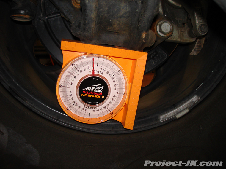
First I like to check the castor. I seldom make any changes to this adjustment. It is also not that critical to have exactly to some spec, but it is important to have each side even. For this I use the Magnetic base protractor. It is accurate to .5 degrees which I think is adequate for castor measurement. On a Strut car I simply place it on the strut and measure the angle of the strut. This may be off slightly from the spec books, bit the error is correct from side to side and it is fairly close. If you have a car with upper ball joints first check your spindles for a machined flat spot that is parallel with the ball joint axis. If this exists then you can simply place the protractor on this surface and measure castor. Many cars have this machined surface for various reasons. If it doesn't then all is not lost. You will need to make some sort of fixture that will "reach in" to the ball joints. You will need a vertical flat surface with two "arms"
If anyone else has ideas on this please give us a hand.
Here's some links to alignment tools under $200:
http://www.eastwoodco.com/jump.jsp?i...emType=PRODUCT
http://www.eastwoodco.com/jump.jsp?i...emType=PRODUCT
http://members.rennlist.com/captearlg/928aligndiy.html
http://www.pegasusautoracing.com/pro....asp?RecId=883
Now here's some stuff I borrowed from other sites on homemade caster adjustment:
For camber you just need a builder's square ... and a bit of maths! Put the square up against the side of the tyre (it should touch the bottom first if you have negative camber) - then measure from the square to the lower lip of the rim and from the square to the upper lip of the rim. Using the difference between these two measurements and the diameter between the measuring points (plus a bit of Pythagorean Trigonometry) the camber can be worked out.
For castor the builder's square can be used with the wheel off and the weight on a block under the brake disc or lower ball joint to 'eye-ball' the angle to make sure the top ball joint centre is behind the lower one - measuring from the square, the actual angle can be worked out with the help of Pythagoras - again!
First I like to check the castor. I seldom make any changes to this adjustment. It is also not that critical to have exactly to some spec, but it is important to have each side even. For this I use the Magnetic base protractor. It is accurate to .5 degrees which I think is adequate for castor measurement. On a Strut car I simply place it on the strut and measure the angle of the strut. This may be off slightly from the spec books, bit the error is correct from side to side and it is fairly close. If you have a car with upper ball joints first check your spindles for a machined flat spot that is parallel with the ball joint axis. If this exists then you can simply place the protractor on this surface and measure castor. Many cars have this machined surface for various reasons. If it doesn't then all is not lost. You will need to make some sort of fixture that will "reach in" to the ball joints. You will need a vertical flat surface with two "arms"
If anyone else has ideas on this please give us a hand.
JK Junkie
Joined: Mar 2007
Posts: 3,122
Likes: 0
From: Mount Carmel, PA
Cant you just use an angle finder? I got a starrett one for about 20 bucks from msc-direct.com
WOL's Alignment write-up
WOL's Alignment write-up
Last edited by bly109; Feb 24, 2008 at 10:45 AM.